Device control system, control unit and device control method for use therewith

Inactive Publication Date: 2007-10-04
NEC CORP
View PDF4 Cites 28 Cited by
  • Summary
  • Abstract
  • Description
  • Claims
  • Application Information

AI Technical Summary

Benefits of technology

[0024]In a fourth device control system of the present invention, using an upper-level control unit for the control units that control the RF tag reader-writer, the information can be continually acquired from the RF tag without changing the external system at all. Also, in the fourth device control system of the present invention, the lower-level control unit needs to have only the information of the upper-level control unit, whereby the amount of information is reduced. Further, in the fourth device control system of the present invention, the switching of the control is made by the upper-level control unit, whereby it is not required tha

Problems solved by technology

However, with the conventional control unit for the RF tag reader-writer as described above, when a great number of RF tags are detected by a certain RF tag reader-writer, a load occurs if a large amount of control is required, so that the other RF tag reader-writer may

Method used


Image

  • Device control system, control unit and device control method for use therewith
  • Device control system, control unit and device control method for use therewith
  • Device control system, control unit and device control method for use therewith

Examples


embodiment 1

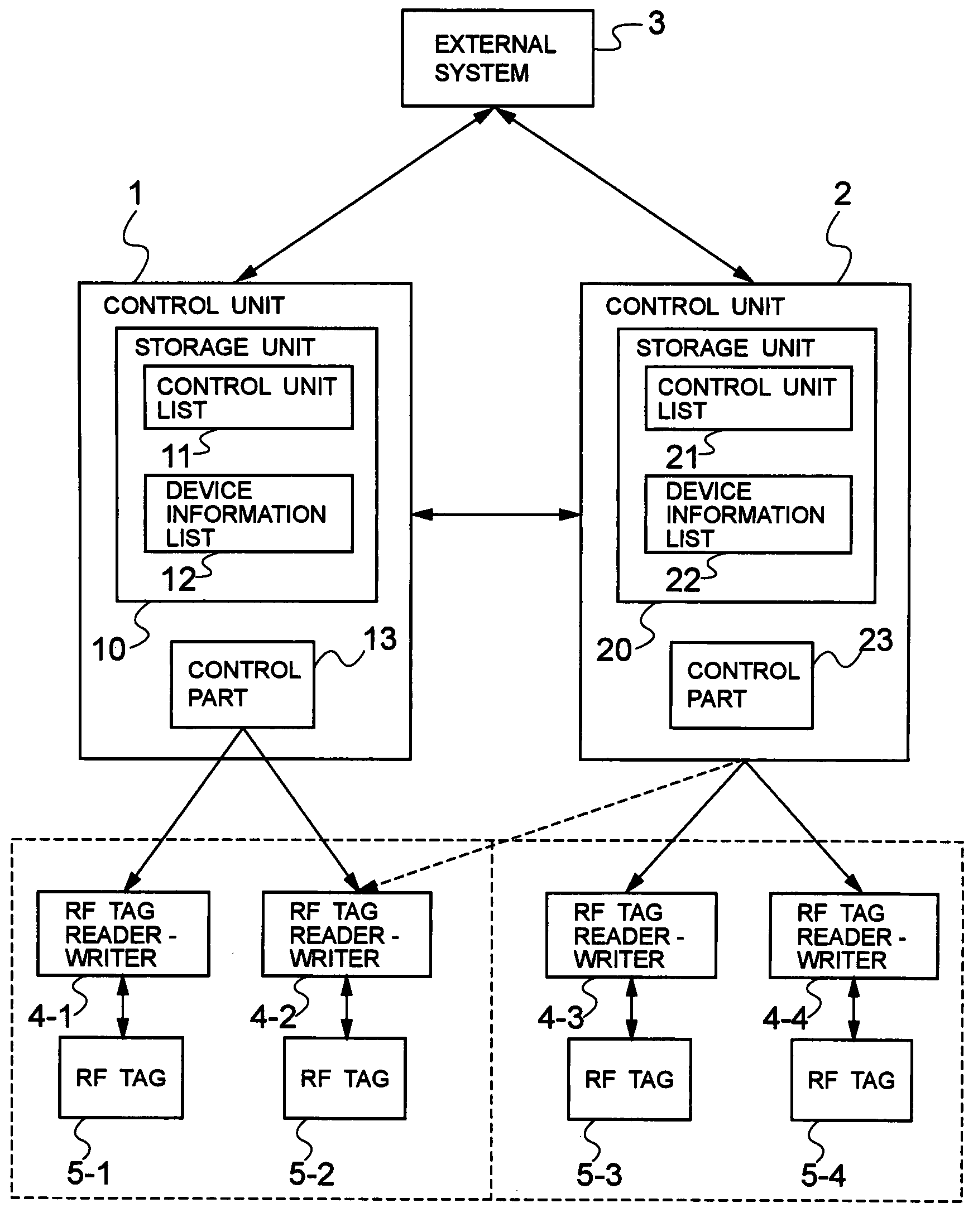
[0039]FIG. 1 is a block diagram showing the configuration of a device control system according to a first embodiment of the present invention. In FIG. 1, the device control system according to the first embodiment of the present invention is the system for controlling a device such as an RF (Radio Frequency) tag reader-writer, and comprises the control units 1 and 2, an external system 3, the RF tag reader-writers 4-1 to 4-4, and the RF tags 5-1 to 5-4.

[0040]A control unit 1 is connected to the RF tag reader-writers 4-1 and 4-2, and supervises and controls the RF tag reader-writers 4-1 and 4-2. A control unit 2 is connected to the RF tag reader-writers 4-3 and 4-4, and supervises and controls the RF tag reader-writers 4-3 and 4-4. The control units 1 and 2 can be connected or disconnected to or from the RF tag reader-writers 4-1 to 4-4 at any time.

[0041]The RF tag reader-writers 4-1 to 4-4 can read the ID (Identification) of the RF rags 5-1 to 5-4, and read or write data by making t...

embodiment 2

[0067]A second embodiment of the present invention will be described below with reference to the drawings. The configuration of a device control system, not shown, according to the second embodiment of the present invention is the same as the device control system according to the first embodiment of the present invention as shown in FIG. 1.

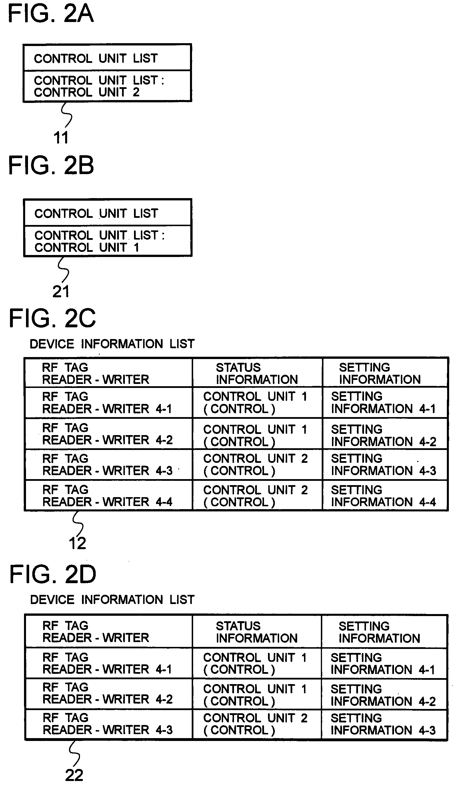
[0068]FIG. 4A is a view showing the organization of a control unit list 11 according to the second embodiment of the present invention, FIG. 4B is a view showing the organization of a control unit list 21 according to the second embodiment of the present invention, FIG. 4C is a view showing the organization of a device information list 12 according to the second embodiment of the present invention, and FIG. 4D is a view showing the organization of a device information list 22 according to the second embodiment of the present invention.

[0069]Referring to FIGS. 4C and 4D, the information registered in the device information lists 12 and 22 are diff...

embodiment 3

[0082]A third embodiment of the present invention will be described below. The configuration of a device control system according to the third embodiment of the present invention is the same as the device control system according to the first embodiment of the present invention as shown in FIG. 1, except that the periodical communication is made between the control units 1 and 2 to supervise the control units 1 and 2 mutually. The control unit 2 can detect that the control unit 1 fails if there is no notification from the control unit 1 or there is no reply to the notification.

[0083]FIG. 6 is a flowchart showing the operation of the control units 1 and 2 according to the third embodiment of the present invention. Referring to FIGS. 1 and 6, the operation of the control units 1 and 2 according to the third embodiment of the present invention will be described below. A process as shown in FIG. 6 is implemented by executing a program held in the storage units 10 and 20 with the control...


PUM


Abstract

The present invention provides a device control system that can automatically switch the control units to eliminate the stop time of a device, and increase the utilization efficiency of the device. If the first control unit detects that the control of an RF tag reader-writer is incomplete from the activity ratio of a control part by supervising the RF tag reader-writer and supervising the periodical communication with the RF tag reader-writer, the control unit confirms whether or not there are one or more notifiable control units by referring to a control unit list. If the first control unit is notifiable to the second control unit, the first control unit notifies the information of the RF tag reader-writer to the second control unit. The second control unit returns a controllable code to the first control unit if the RF tag reader-writer is controllable by referring to the information of the RF tag reader-writer from a device information list.

Description

BACKGROUND OF THE INVENTION[0001]1. Field of the Invention[0002]The present invention relates to a device control system, a control unit and a device control method for use therewith, and more particularly to the control of an RF tag reader-writer for reading the ID (Identification) of an RF (Radio Frequency) tag, or reading or writing data by making wireless communication with the RF tag.[0003]2. Description of the Prior Art[0004]The RF tag reader-writer is a device that reads the ID of the RF tag, or reads or writes data by making the wireless communication with the RF tag (e.g., refer to Japanese Patent Laid-Open No. 2001-043326 and Japanese Patent Laid-Open No. 2001-092930). The RF tag reader-writer is often controlled by a control unit having the control software incorporated into a PC (Personal Computer).[0005]The control unit controls the RF reader-writer to make the settings and read the ID of the RF tag. Also, the control unit notifies the ID and so on read from the RF tag ...

Claims


Application Information

Patent Timeline
IPC IPC(8): G05B23/02
CPCG05B23/0289
Inventor YASUDA, JUNICHI
Owner NEC CORP
Why Eureka
Try Eureka