RFID tag reading rate

a technology of radio frequency identification and reading rate, which is applied in the direction of burglar alarm mechanical actuation, burglar alarm by hand-portable article removal, instruments, etc., can solve the problem of reducing and achieve the effect of improving the reading rate of rfid tags

Active Publication Date: 2007-10-04
NEC CORP
View PDF5 Cites 14 Cited by
  • Summary
  • Abstract
  • Description
  • Claims
  • Application Information

AI Technical Summary

Benefits of technology

[0009]It is therefore an object of the present invention to provide an RFID system and RFID reading method that can improve the reading rate for RFID tags.
[0015]According to this configuration, it is possible to detect the position of an RFID tag and, based on the detected position, select an antenna optimal for reading the RFID tag, e.g., being close to the RFID tag, and to activate the antenna preferentially to read the RFID tag. Consequently, the reading rate for RFID tags can be improved in the RFID system as a whole.
[0019]According to the configuration, it is possible to detect the position and inclination angle of the RFID tag, and based on the detected position and inclination angle, select an antenna optimal for reading the RFID tag, e.g., being close to and facing the RFID tag, and activate that antenna preferentially to read the RFID tag. Thus, the reading rate for RFID tags can be further improved in the RFID system as a whole.

Problems solved by technology

However, a problem is that the reading rate for RFID tags can decrease depending on the position of RFID tags attached to articles or the like.

Method used


Image

  • RFID tag reading rate
  • RFID tag reading rate
  • RFID tag reading rate

Examples


first embodiment

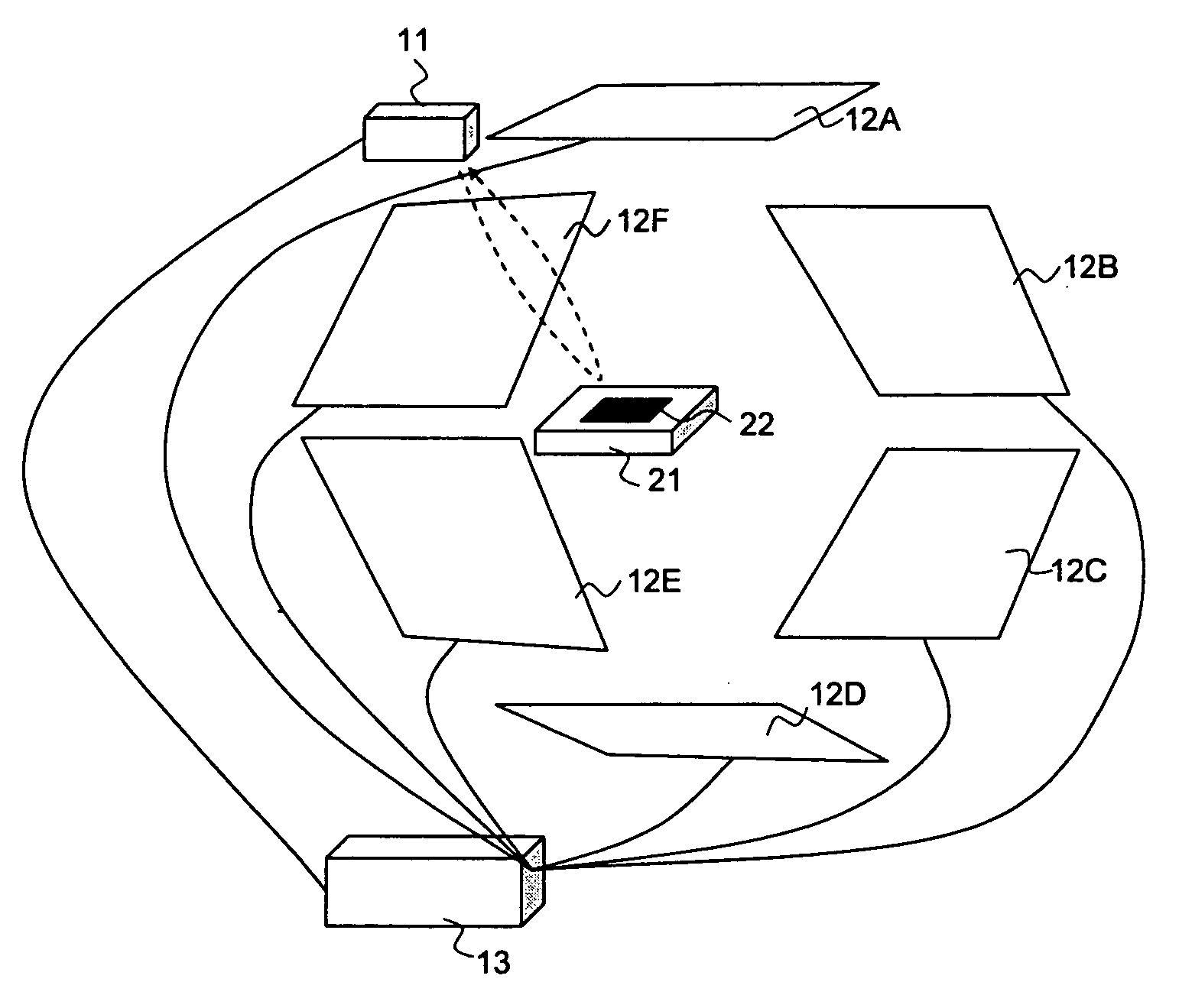
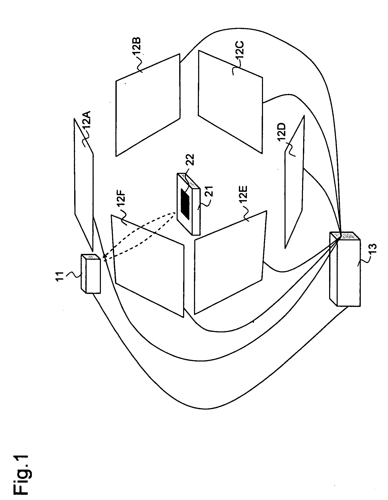
[0032]FIG. 1 shows the configuration of an RFID system according to the first embodiment of the present invention.

[0033]Referring to FIG. 1, the RFID system of the embodiment includes distance sensor 11, a plurality of antennas 12A to 12F, and RFID reader 13.

[0034]Distance sensor 11 serves as a position detection unit for detecting the distance to the position of RFID tag 22 which is attached to article 21 and for outputting the detected value to RFID reader 13 as the result of position detection. This embodiment provides distance sensor 11 above article 21 assuming that RFID tag 22 is attached to the upper surface of article 21, so that distance sensor 11 detects the distance to the upper surface of article 21 and the detected value is assumed to be the distance to RFID tag 22.

[0035]Antennas 12A to 12F are installed in a loop around article 21 and read data from RFID tag 22 under control of RFID reader 13 and output the result of reading to RFID reader 13. Specifically, when activa...

second embodiment

[0049]FIG. 3 shows the configuration of an RFID system according to the second embodiment of the present invention.

[0050]Referring to FIG. 3, the RFID system of this embodiment is different from the first embodiment shown in FIG. 1 in that it has camera 14 and image recognition unit 15 as the position detection unit instead of distance sensor 11.

[0051]Camera 14 serves as an image taking unit that takes an image of RFID tag 22 and outputs the taken image to image recognition unit 15. To take an image of RFID tag 22 reliably, it is preferable that two or more cameras 14 are provided so that an image of RFID tag 22 is taken from different angles by those cameras. However, when it is assumed that RFID tag 22 is attached at a fixed position, there may be only one camera 14 as long as camera 14 is positioned such that it can take an image of RFID tag 22 attached at the fixed position.

[0052]Image recognition unit 15 performs image recognition of an image of RFID tag 22 output from camera 1...

third embodiment

[0057]FIG. 5 shows the configuration of an RFID system according to the third embodiment of the present invention.

[0058]Referring to FIG. 5, the RFID system of this embodiment is different from the first embodiment shown in FIG. 1 in that it has RFID readers 13A to 13F which are connected to antennas 12A to 12F respectively and multi-reader control unit 16 which is connected to RFID readers 13A to 13F to control RFID readers 13A to 13F.

[0059]The result of reading RFID tag 22 by antennas 12A to 12F is input to RFID readers 13A to 13F, respectively.

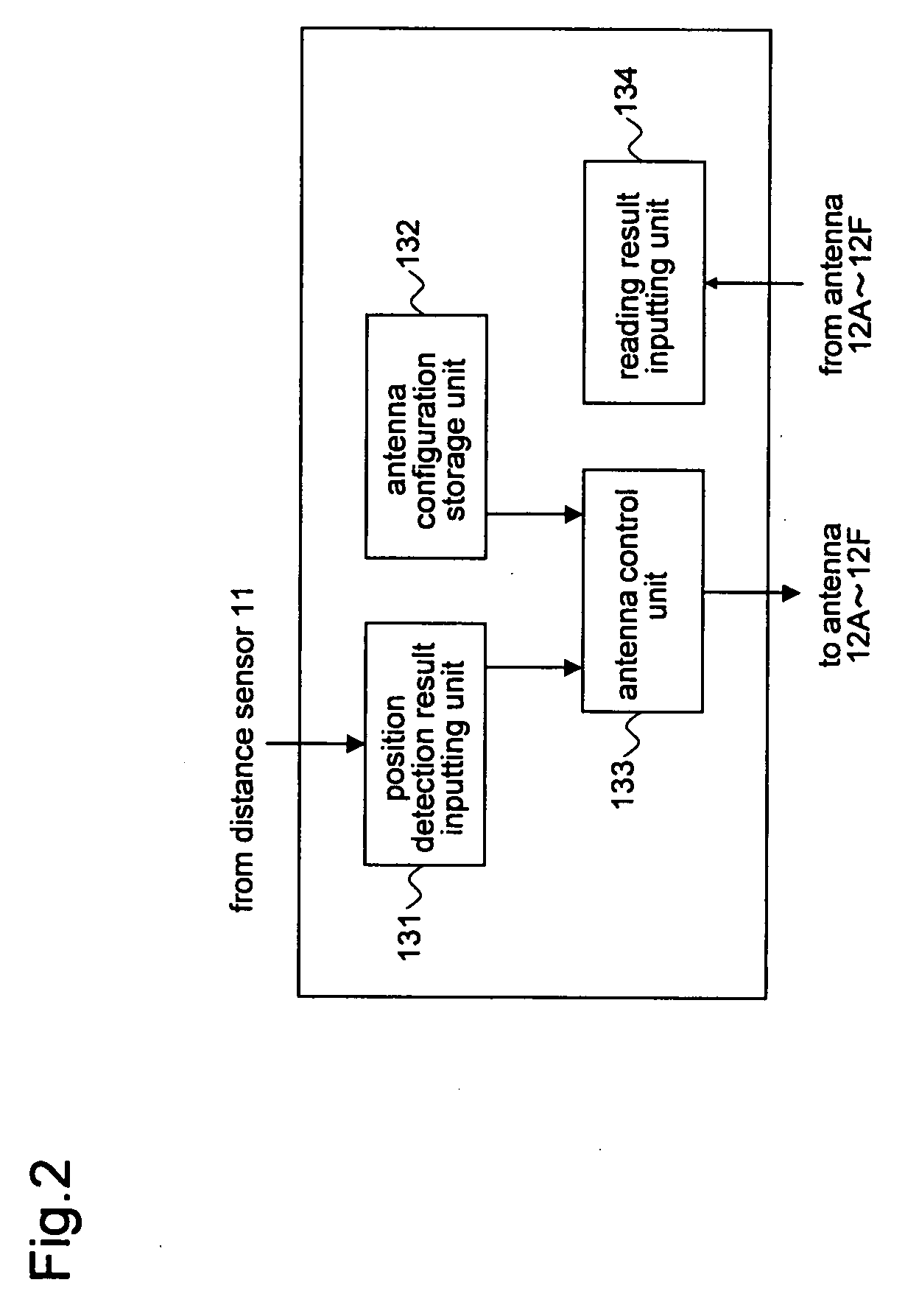
[0060]The configuration of multi-reader control unit 16 is similar to that of RFID reader 13 shown FIG. 2 with the antennas replaced with RFID readers.

[0061]Except for the above-described configuration and operations, this embodiment is similar to the first embodiment.


PUM


Abstract

An RFID system of the present invention has a plurality of antennas for reading data from an RFID tag; an antenna configuration storage unit for prestoring a position of each of the plurality of antennas; a position detection unit for detecting a position of the RFID tag; and an antenna control unit for selecting one or more of the antennas that read the RFID tag, based on the position of the RFID tag detected by the position detection unit and on the position of each of the plurality of antennas stored in the antenna configuration storage unit, and for preferentially activating the selected one or more of the antennas.

Description

[0001]This application is based upon and claims the benefit of priority from Japanese Patent Application No. 2006-70800 filed on Mar. 15, 2006, the content of which is incorporated by reference.BACKGROUND OF THE INVENTION[0002]1. Field of the Invention[0003]The present invention relates to a Radio Frequency Identification (RFID) system and an RFID reading method for reading data from an RFID tag.[0004]2. Description of the Related Art[0005]In recent years, it has become increasingly common to perform article management by attaching RFID tags on which data about articles is written, and reading data from those RFID tags. To ensure accurate article management, the requirement is that data must be accurately read from RFID tags.[0006]Accordingly, as RFID systems for article management, multi-antenna systems that have a plurality of antennas for reading data from RFID tags have recently come into use (see JP-A-2002-074279 and JP-A-2002-356227). In addition, multi-reader systems that con...

Claims


Application Information

Patent Timeline
Patent Type & Authority Applications(United States)
IPC IPC(8): G08B13/14H04Q5/22
CPCG06K7/0008G06K7/10316H01Q21/205H01Q1/2216H01Q3/242G06K7/10425
Inventor AKIGUCHI, MAKIKOTAKEUCHI, SHOHEI
Owner NEC CORP
Why Eureka
Try Eureka