RFID reading system using RF grating

a reading system and rfid technology, applied in the field of radiofrequency communication, can solve the problems of rfid tags in general, passive tags specifically, not having enough processing power or memory to perform cryptographic authentication or authorization functions, rfid systems can be vulnerable to attacks, lost productivity or wasted products, etc., to reduce rf crosstalk, reduce the range of positions, and restrict the rf energy from the reader

Active Publication Date: 2013-12-26
EASTMAN KODAK CO
View PDF6 Cites 13 Cited by
  • Summary
  • Abstract
  • Description
  • Claims
  • Application Information

AI Technical Summary

Benefits of technology

[0018]An advantage of this invention is that it restricts the locations from which a reader can communicate with a tag. This reduces the range of positions from which a skimmer can monitor tag transmissions. Various embodiments use standard readers and tags and do not require custom security electronics or protocols. Various embodiments use the enclosure to restrict RF energy from the reader to communicate with only one tag at a time. Various embodiments reduce RF crosstalk and permit increasing the read rate.

Problems solved by technology

However, RFID tags in general, and specifically passive tags, often do not have enough processing power or memory to perform cryptographic authentication or authorization functions, such as secure hashing with time-varying salt.
As a result, RFID systems can be vulnerable to attacks in which a rogue (non-authorized) reader placed near a tag reads and stores that tag's data.
This can result in incorrect products being used in industrial or commercial processes, or mishandled inventory in a retail environment, possibly resulting in lost productivity or wasted product.
However, the blocker will disrupt all accesses, not just unauthorized access.
However, none of these schemes reduces the probability of passive monitoring by a skimmer during an authorized read of the tag.
This can result in contention between tags for the bandwidth, reducing the number of tags that can be read in a certain amount of time.
However, this reference does not recognize difficulties that can be encountered in reading RFID tags attached to RF-attenuating containers of liquid.
This shield affects the radiation pattern of the antennas to reduce their power in the direction of the unwanted objects, but does not control access to tags in the direction of wanted objects.
However, the blocker will disrupt all accesses, not just unauthorized access.
However, this scheme is not applicable to environments such as retail stockrooms or production lines in which the tagged items are not confined in a cabinet.
Similar problems exist with reading tags in production environments.
Communicating with the correct tag, especially when instances are closely spaced on the conveyor, can be difficult.
However, tunnels can be very long for LF or HF RFID operation.
Tunnels also restrict access to the conveyor or instances on it, making service and visual inspection more difficult.

Method used


Image

  • RFID reading system using RF grating
  • RFID reading system using RF grating
  • RFID reading system using RF grating

Examples


Embodiment Construction

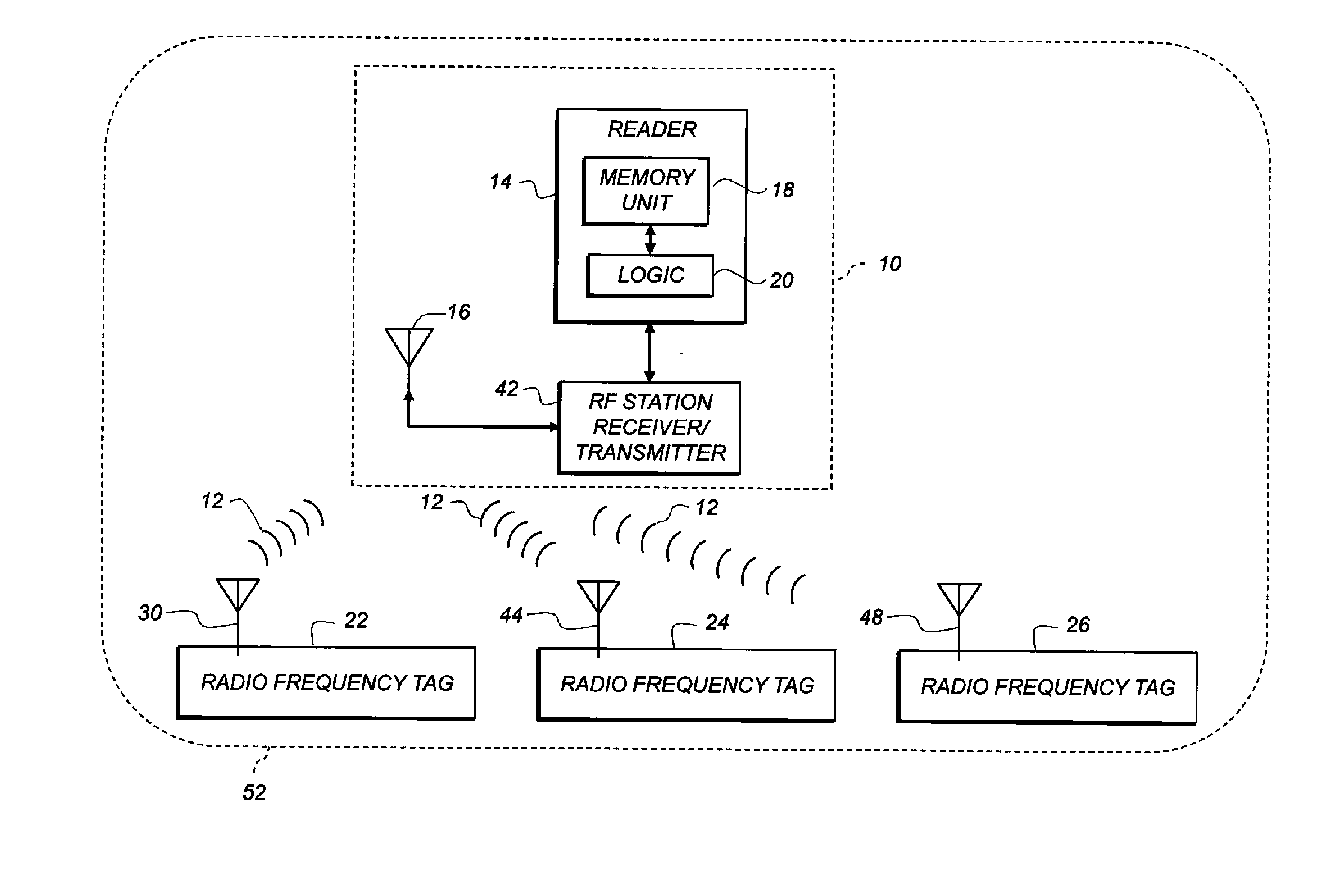
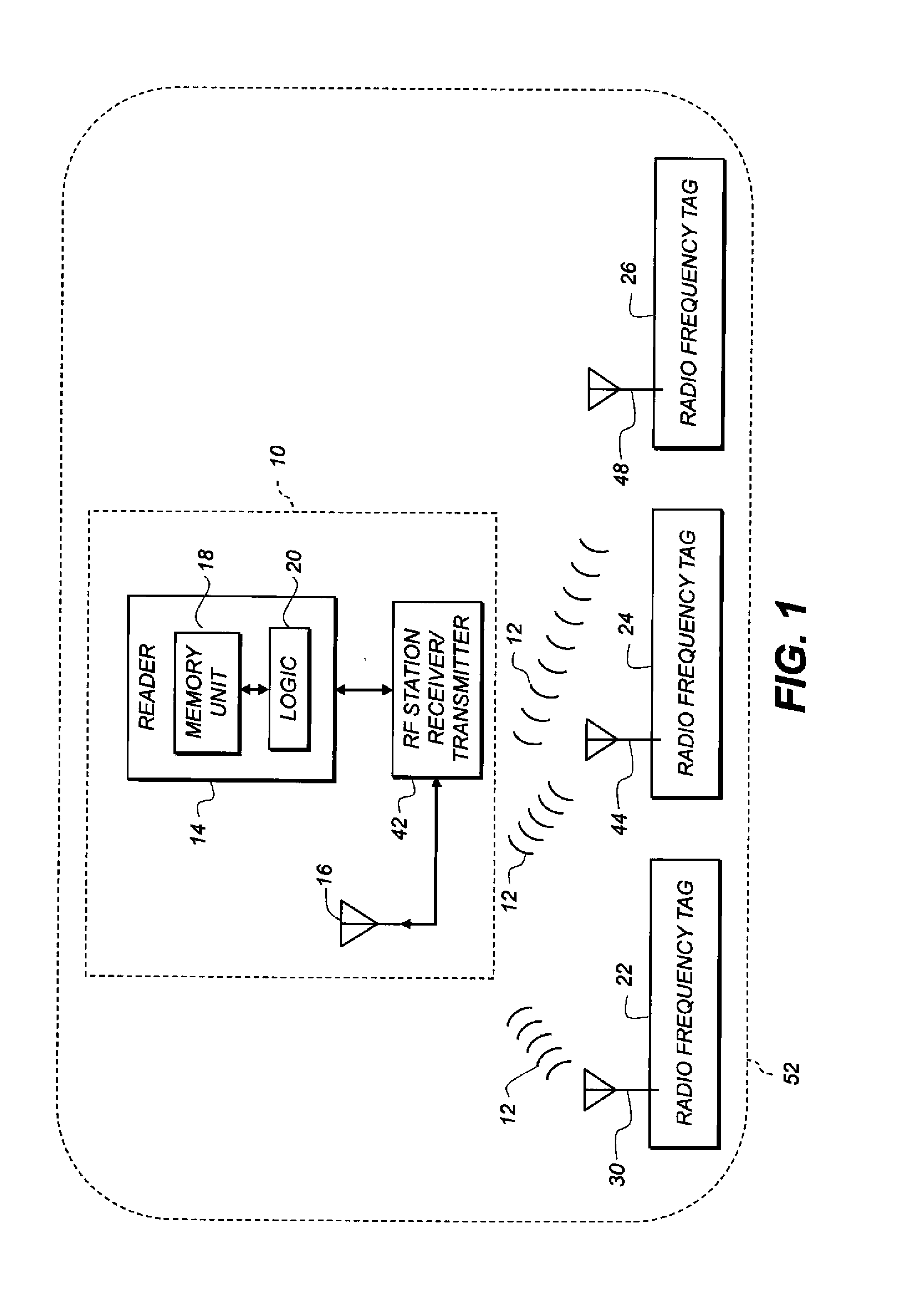
[0026]As used herein, the term “uplink” refers to communications from an RFID tag to a reader, and “downlink” to communications from a reader to a tag. These terms are used regardless of which side initiates the communication.

[0027]In the following description, some embodiments will be described in terms that would ordinarily be implemented as software programs. Those skilled in the art will readily recognize that the equivalent of such software can also be constructed in hardware. Because image manipulation algorithms and systems are well known, the present description will be directed in particular to algorithms and systems forming part of, or cooperating more directly with, methods described herein. Other aspects of such algorithms and systems, and hardware or software for producing and otherwise processing the image signals involved therewith, not specifically shown or described herein, are selected from such systems, algorithms, components, and elements known in the art. Given ...


PUM


Abstract

Apparatus for reading an RFID tag includes an RF-blocking enclosure having a port and adapted to receive through the port a non-RFID-active object having an RFID tag affixed thereto. An RFID reader has a reader antenna located outside the enclosure. The antenna transmits an RF downlink signal in a particular direction. An RF grating is arranged between the reader antenna and the port so that, after the enclosure receives the object having the tag, the port is located in the transmit direction from the reader antenna, and RF energy transmitted from the reader antenna has a selected linear polarization after passing through the grating.

Description

CROSS-REFERENCE TO RELATED APPLICATIONS[0001]This application is co-filed with and has related subject matter to U.S. patent application Ser. No. ______ (attorney docket no. K000867), filed herewith, titled “RFID SYSTEM WITH MULTIPLE TAG TRANSMIT FREQUENCIES;” U.S. patent application Ser. No. ______ (attorney docket no. K000865), filed herewith, titled “RFID SYSTEM WITH ENCLOSURE AND INTERFERENCE PATTERN;” U.S. patent application Ser. No. ______ (attorney docket no. K000911), filed herewith, titled “RFID SYSTEM WITH BARRIERS AND KEY ANTENNAS;” U.S. patent application Ser. No. ______ (attorney docket no. K000966), filed herewith, titled “RFID SYSTEM WITH MULTIPLE READER TRANSMIT FREQUENCIES;” U.S. patent application Ser. No. ______ (attorney docket no. K000863), filed herewith, titled “READING RFID TAG USING ANTENNA WITHIN ENCLOSURE;” and U.S. patent application Ser. No. ______ (attorney docket no. K000965), filed herewith, titled “RFID SYSTEM WITH CONFIGURABLE RF PORT;” all of which...

Claims


Application Information

Patent Timeline
Patent Type & Authority Applications(United States)
IPC IPC(8): G06K7/01
CPCG06K19/07327G06K7/01
Inventor ZOGG, EDWARDHINMAN, MARK P.WHITE, CHRISTOPHER J.
Owner EASTMAN KODAK CO
Why Eureka
Try Eureka