Flap-cover aneurysm stent

Inactive Publication Date: 2006-02-09
STRYKER EURO OPERATIONS HLDG LLC +1
View PDF35 Cites 32 Cited by
  • Summary
  • Abstract
  • Description
  • Claims
  • Application Information

AI Technical Summary

Benefits of technology

[0012] In some embodiments, the stent may comprise a first closed serpentine band extending at a first end of the stent and a second closed serpentine band at a second end of the stent. One or more interconnecting elements may extend between the first and second serpentine bands. The stent may have a treatment side wherein the plurality of flaps are located, and a non-treatment side disposed opposite the treatment side. The non-treatment side may have one or more openings therethrough.
[0013] In some embodiments, a stent may comprise a plurality of overlapping flaps and the stent may be constructed and arranged such that the extent of the overlap decreases upon expansion of the stent. The flaps may form a patch of a predetermined shape, which may be substantially circular when the stent is expanded.

Problems solved by technology

The dilation may be packed with the detachable coil, thereby obstructing blood flow such that the blood clots within the dilation, thereby forming an occlusion.

Method used


Image

  • Flap-cover aneurysm stent
  • Flap-cover aneurysm stent
  • Flap-cover aneurysm stent

Examples


Embodiment Construction

[0024] While this invention may be embodied in many different forms, there are described in detail herein specific embodiments of the invention. This description is an exemplification of the principles of the invention and is not intended to limit the invention to the particular embodiments illustrated.

[0025] For the purposes of this disclosure, like reference numerals in the figures shall refer to like features unless otherwise indicated.

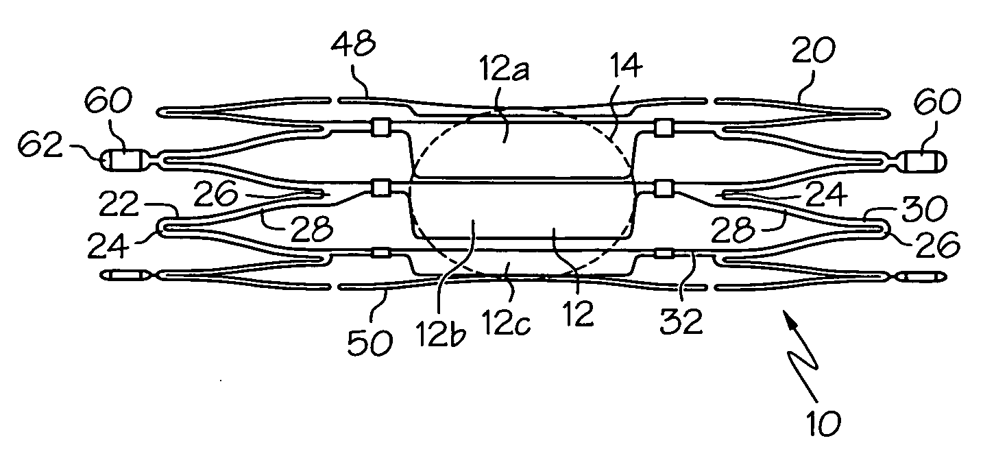
[0026]FIG. 1 shows a pattern for an embodiment of a stent 10 which may comprise an expandable framework 20 and a plurality of flaps 12. The stent 10 may be positioned within a bodily vessel at an aneurysm site such that the flaps 12 are arranged to block blood flow into the aneurysm.

[0027] A stent 10 may have a treatment side and a non-treatment side. The treatment side may be defined generally by the existence of flaps 12. The treatment side may have a first edge 48 and a second edge 50 defining a divide between the treatment side and the non-t...


PUM


Abstract

A stent may comprise an expandable framework and a plurality of flaps. Adjacent flaps may overlap one another to form a wall region of predetermined shape. The stent may be delivered to an aneurysm site and positioned such that the wall region blocks fluid flow into the aneurysm.

Description

BACKGROUND OF THE INVENTION [0001] Implantable medical devices, such as a stents, grafts, stent-grafts and the like, and delivery assemblies for implantable medical devices are utilized in a number of medical procedures and situations, and as such their structure and function are generally known in the art. [0002] An aneurysm is generally a localized blood-filled dilation of a vessel. One method of treating an aneurysm is to place a porous stent in the vessel at the aneurysm site. A porous stent can close an aneurysm over a period of time, such as a week. [0003] Another method of treating an aneurysm includes the use of Guglielmi electrolytically detachable coils, for example as described in U.S. Pat. No. 5,947,962, incorporated herein by reference. The dilation may be packed with the detachable coil, thereby obstructing blood flow such that the blood clots within the dilation, thereby forming an occlusion. [0004] There remains a need for a device that is relatively easy to position...

Claims


Application Information

Patent Timeline
Patent Type & Authority Applications(United States)
IPC IPC(8): A61F2/06A61B17/12A61F2/82
CPCA61F2/91A61F2/915A61F2002/825A61F2230/0054A61F2002/9155A61F2002/91558A61F2002/823A61F2002/91541
Inventor MUSBACH, FRANK
Owner STRYKER EURO OPERATIONS HLDG LLC
Why Eureka
Try Eureka