Electric miter saw

a technology miter saw, which is applied in the field of electric miter saw, can solve the problems of inability to cut with some saws, inability to accurately localize, and decrease in cutting precision, and achieve the effects of improving the cutting range of current miter saw, efficient utilization, and simple and steady mounting

Inactive Publication Date: 2007-04-05
NIG BO YANG MING ELECTRIC TOOLS
View PDF15 Cites 31 Cited by
  • Summary
  • Abstract
  • Description
  • Claims
  • Application Information

AI Technical Summary

Benefits of technology

[0024] First, the space between the cutting table and the base can be efficiently utilized so that the slide rod can extend under the surface and its exposed part is shorter because the slide rod is secured under the surface. Therefore, the supporting member will slide more safely and smoothly on the slide rod. Secondly, the slide rod need only be housed directly on the localization cavity that is preserved beneath the cutting table and processed and fixed directly with a forcing bolt, or secured by the location aperture and securing panel. The mounting is very simple and steady, and the cutting range of the current miter saw is improved. In the miter saws of the same dimension, in order to increase the cutting range, a manufacturer will choose the increase of the stroke (to increase the length of the slide rod) to meet a consumer's need. Hence, the apparent dimension of a miter saw is increased so that the proportion of the whole saw and external packing dimension are affected. If the slide rod is mounted beneath the cutting table, the huge space beneath the surface can be utilized to maximum degree. If one end of the slide rod is extended into the cutting table by appropriate length, the proportion of the whole saw can be maintained and the external packing dimension controlled. Also, the cutting stroke will be increased and the whole saw will have a beautiful appearance, a simple configuration, which will bring an easy manufacture and a lower cost. Because of the sliding and supporting connection of the supporting member and slide rod, the connection will become compact, it is very convenient to be operated and the operation stability of the saw will be increased.
[0025] When the saw is not in use and in storage instead, loosen the securing screw, move the exposed portion of the slide rod into the table and then secure it. In that way, the space for storage and packing can be reduced and it is convenient to be stored and packed. The design of the saw's whole configuration is reasonable and simple. It is convenient to be used and brings about a good effect. The mechanism to control the opening and closing of the flexible blade guard is a gear-driven one consisting of a tension rod, a rack and gear. The configuration design is reasonable and simple, and reduce the precision of process, production and installation of every part. Even if there exists some errors, they can eliminated with the adjustment of the first engaging position of the rack and gear. It is easy to for the flexible blade guard to be in position. There exists no dead center in the design of configuration and no position block. The rotation is very flexible. It is very convenient to be maintained. With the adjustment of the teeth ratio between the rack and gear, the opening speed of the flexible blade guard can be adjusted so that the mechanism property of the saw will be increased.

Problems solved by technology

If a workpiece is too wide, it cannot be cut by some saws.
There are disadvantages as well, for example, because the localization aperture beneath the cutting table is supported by a slidable extension, it is easy to shake, which can cause the inaccuracy in localization and decrease of cutting precision and needs to be improved.
However, the slide rod secured under the cutting table gives the saw a non-beautiful and a slightly large appearance.
Therefore, most of space under the cutting table cannot be utilized fully and the proportion of the machine is affected.
And it can cause the reduction of the area of the cutting table that can be utilized efficiently and therefore affects the width of its cutting stroke, which are all needed to be improved.
On the other hand, there is no flexible blade guard on traditional electric saws and there exists some hidden troubles of safety.
Though it is simple in configuration, low in manufacturing cost and easily implemented, some advantages have exposed in the practical application and they cannot be overcome, for example, the requirements of the process and installation of the link bar and slot are very high.
If some errors appear during the process or installation, a dead center will be caused and the link rod mechanism will not be controlled flexibly or even be blocked dead, which will easily cause safety accidents during operation.
In case those disadvantages are formed, it is very difficult to correct itself by means of adjustment of the installation position.

Method used


Image

  • Electric miter saw
  • Electric miter saw
  • Electric miter saw

Examples


Embodiment Construction

[0040] Referring to the drawings, a detailed description of the invention is as follows:

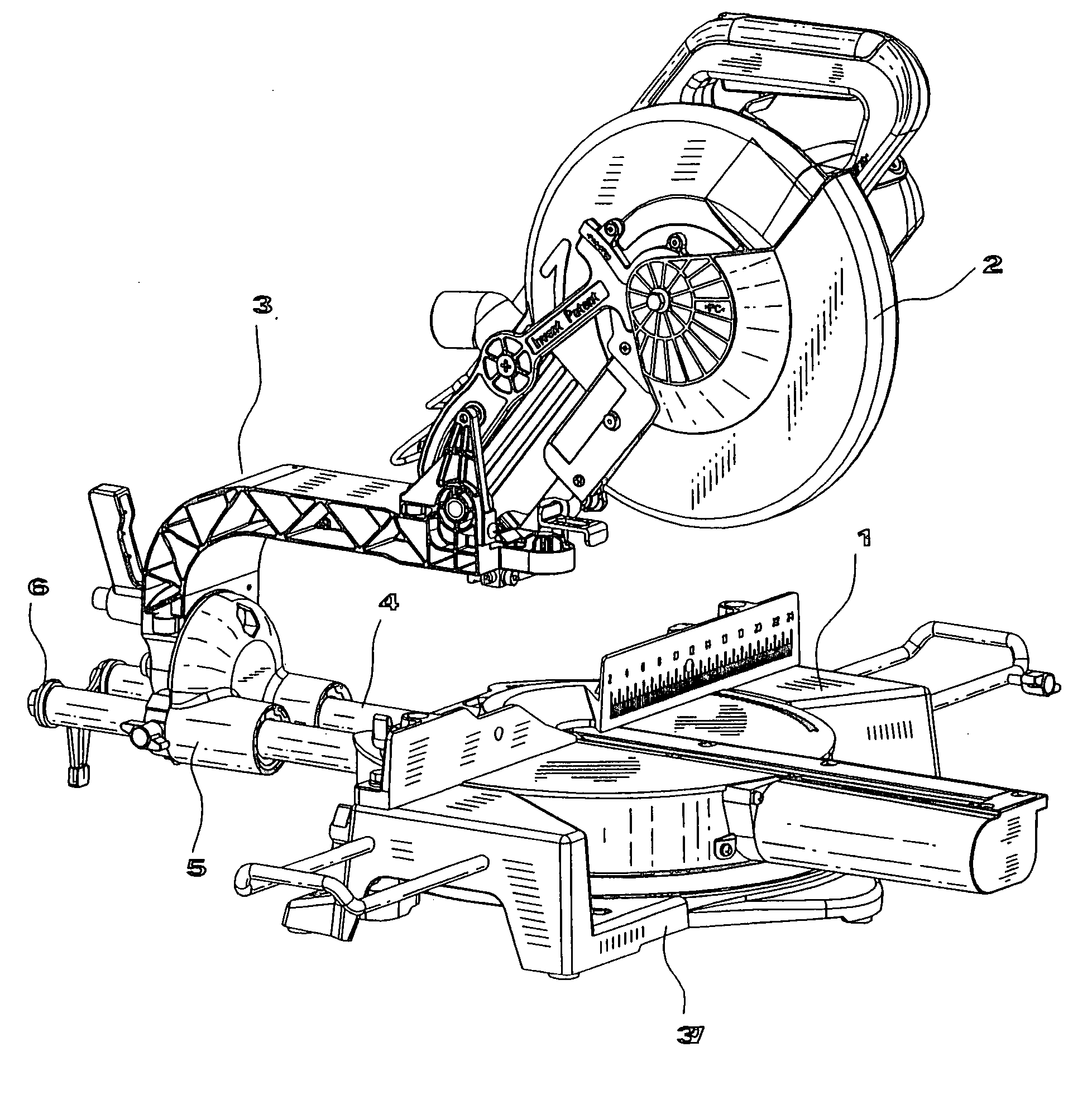
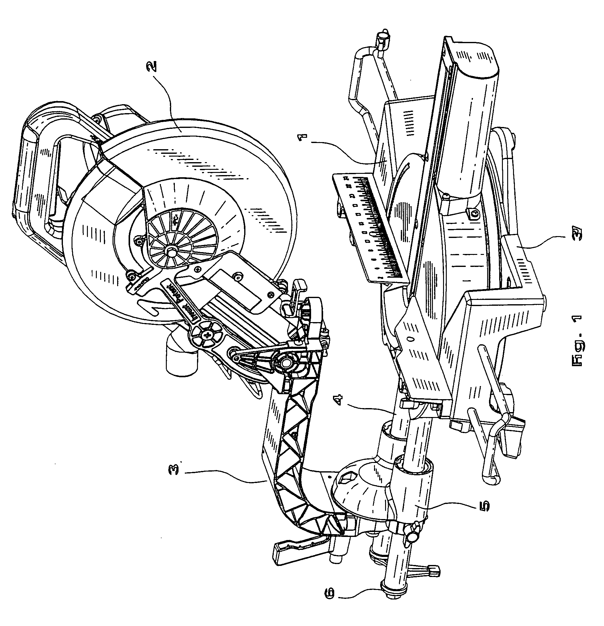
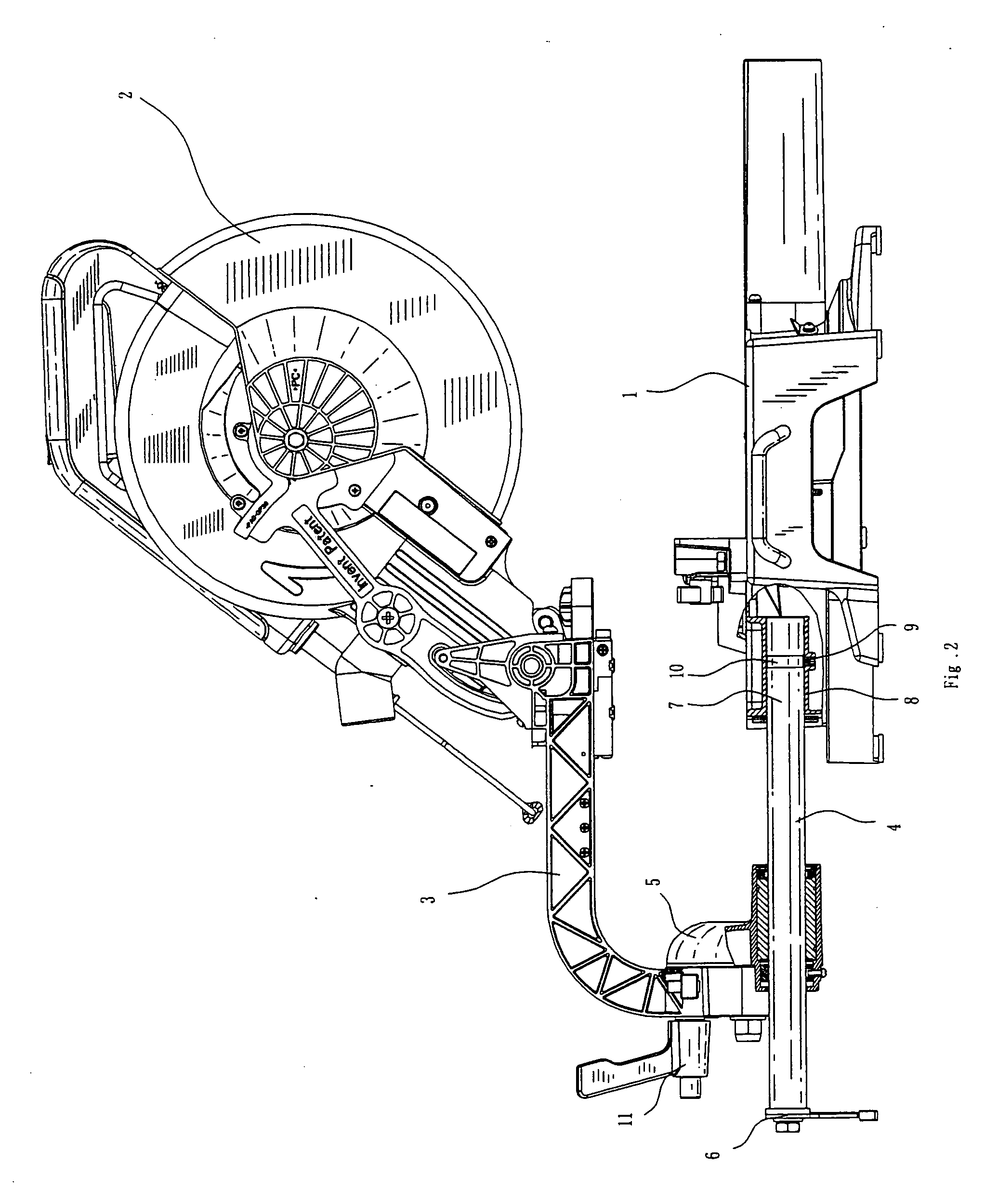
[0041] As shown in FIGS. 1, 2, 3 and 13, an electric miter saw includes components such as a base 37, a cutting table 1, a cutting member 2 and a link arm 3. The cutting table 1 is mounted on the base 37. At one side beneath the cutting table 1 are formed two localization cavities 7 (FIG. 2), which are housed left and right symmetrically beneath the table with the central line as a benchmark. There are threaded apertures on the walls 8 of the cavities. There are localization slots 10 at the inserting end for the slide rod 4's insertion of the cavity. The localization slot 10 is usually a ring-shaped slot. After the slide rod 4 is inserted into the localization cavities 7, the threaded bolt 9 is extended into the threaded aperture for its inner end to be pushed into the localization slot 10 at the inserting end to secure the slide rod beneath the cutting table 1. The outer end of the slide rod 4 ...


PUM

PropertyMeasurementUnit
flexibleaaaaaaaaaa
shapeaaaaaaaaaa
transparentaaaaaaaaaa

Abstract

An electric miter saw includes a base, a cutting table, a cutting member and a link arm. The cutting table is mounted on the base. The upper portion of the link arm is connected to a cutting member with the cutting saw blade driven by a motor. The lower portion of the link arm is connected to the upper portion of a supporting member and secured by a threaded central bolt. The linear ball bearing is mounted in the inner aperture of the supporting member, which is slidably connected to the slide rod by a linear ball bearing. At the outer end of the slide rod is mounted a position limit socket. The inner end of the slide rod is connected and secured beneath the cutting table via a releasable securing configuration mentioned above. A flexible blade guard is also provided.

Description

[0001] This is a divisional application claiming the priority of U.S. patent application Ser. No. 10 / 840,811, filed May 7, 2004.BACKGROUND OF THE INVENTION [0002] This invention relates the technical field of an electric miter saw. [0003] Because of the development in the construction material industry, an electric saw in the electric tools is widely used to cut metal tubes, angle irons, channel steels, various kinds of timber and stones. Hence, an electric saw has a large market, and science and technology staffs are developing various types of electric saws. A cutting width limit exists in the traditional and common electric saws. [0004] If a workpiece is too wide, it cannot be cut by some saws. So, an electric saw with an adjustable cutting width has been developed, such as U.S. Pat. No. 5,054,352, in which a retractable slide rod mechanism is adopted. One end of the slide rod is housed under a cutting table and the other end can be rotatably connected to the lower end of a link ...

Claims


Application Information

Patent Timeline
Patent Type & Authority Applications(United States)
IPC IPC(8): B27B5/20
CPCB23D45/048B27B5/29B27G19/02Y10T83/7788Y10T83/606Y10T83/7763Y10T83/7693Y10T83/7734
Inventor HU, GUI QIANG
Owner NIG BO YANG MING ELECTRIC TOOLS
Why Eureka
Try Eureka