Backlight module

Inactive Publication Date: 2007-10-04
CORETRONIC
View PDF8 Cites 11 Cited by
  • Summary
  • Abstract
  • Description
  • Claims
  • Application Information

AI Technical Summary

Benefits of technology

[0009]The present invention provides a backlight mod

Problems solved by technology

However, the brightness of the light sources may decrease with time.
Therefore, it is currently an important issue to extend the lifetime of the backlight module.
However, this may lower the brightness

Method used


Image

  • Backlight module
  • Backlight module
  • Backlight module

Examples


Example

The First Embodiment

Driving Light Source Sets by Turns According to Predetermined Time Interval

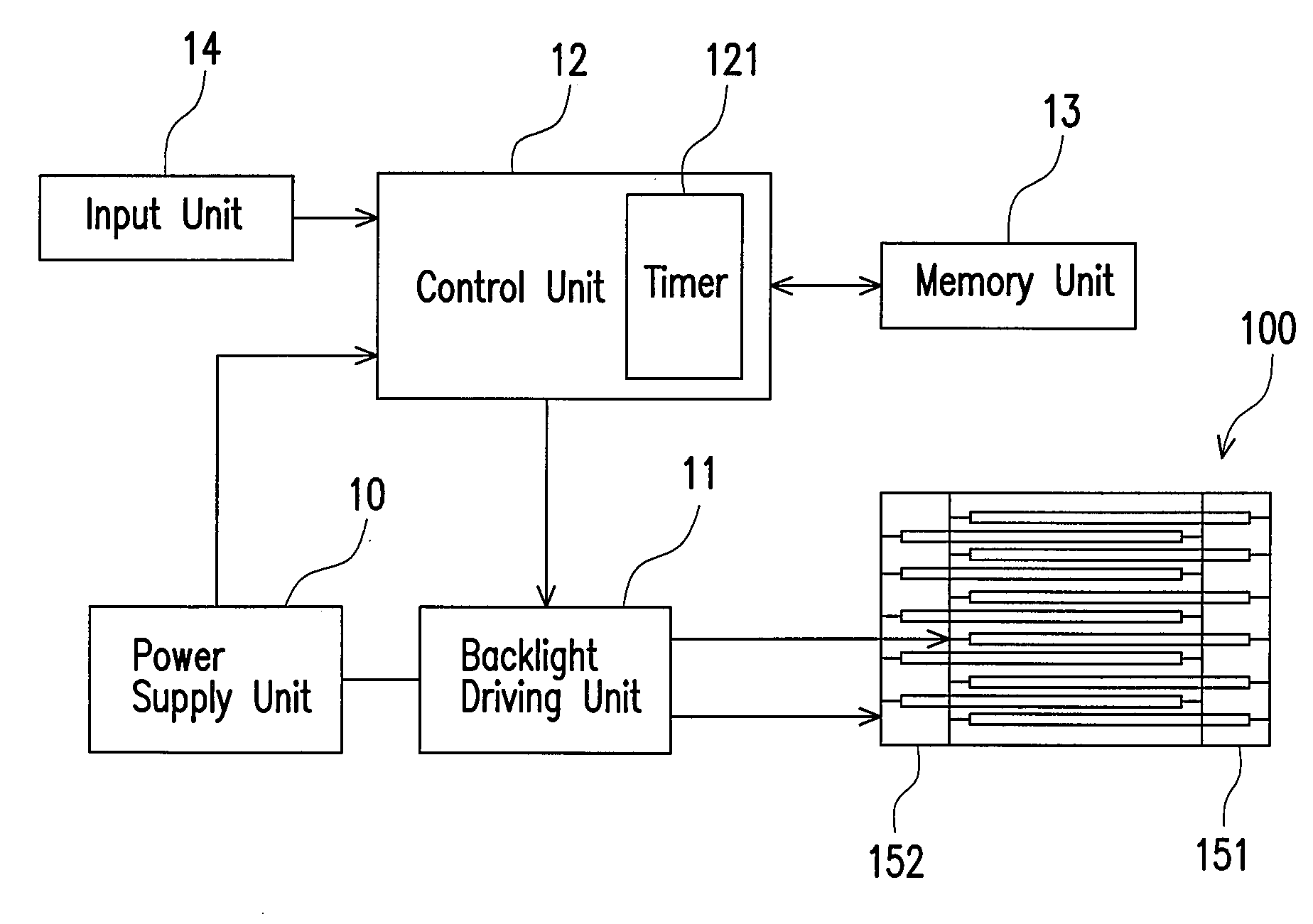
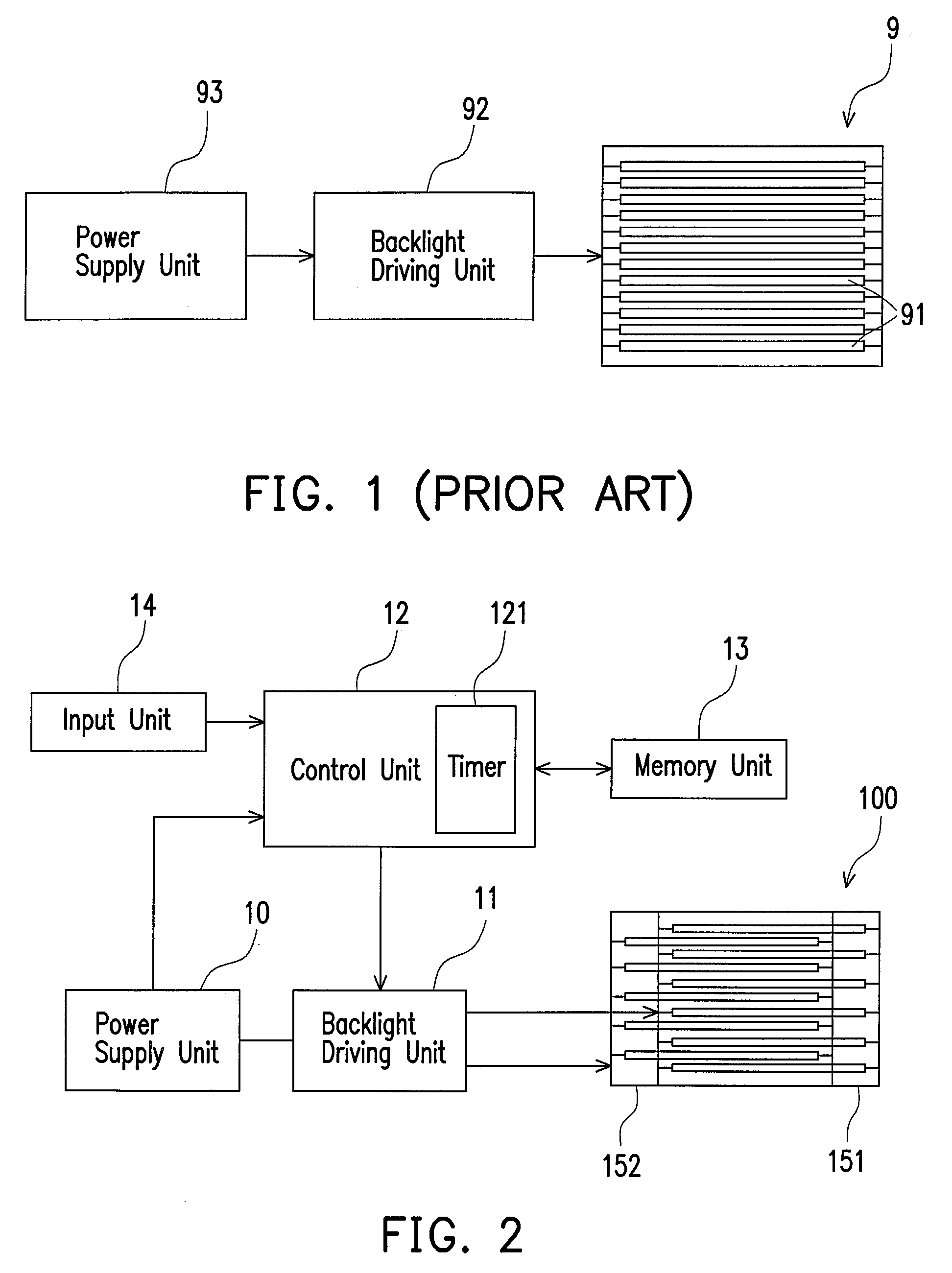
[0029]Referring to FIG. 2, a backlight module 100 according to the first embodiment of the present invention includes a control unit 12, a power supply unit 10, an input unit 14, a memory unit 13, a backlight driving unit 11, a first light source set 151, and a second light source set 152.

[0030]The control unit 12 is connected to the power supply unit 10, the backlight driving unit 11, a memory unit 13, and the input unit 14. The control unit 12 includes a timer 121 for timing the period of power supply provided by the power supplying unit 10. The power supplying unit 10 is adapted for supplying power to the backlight driving unit 11.

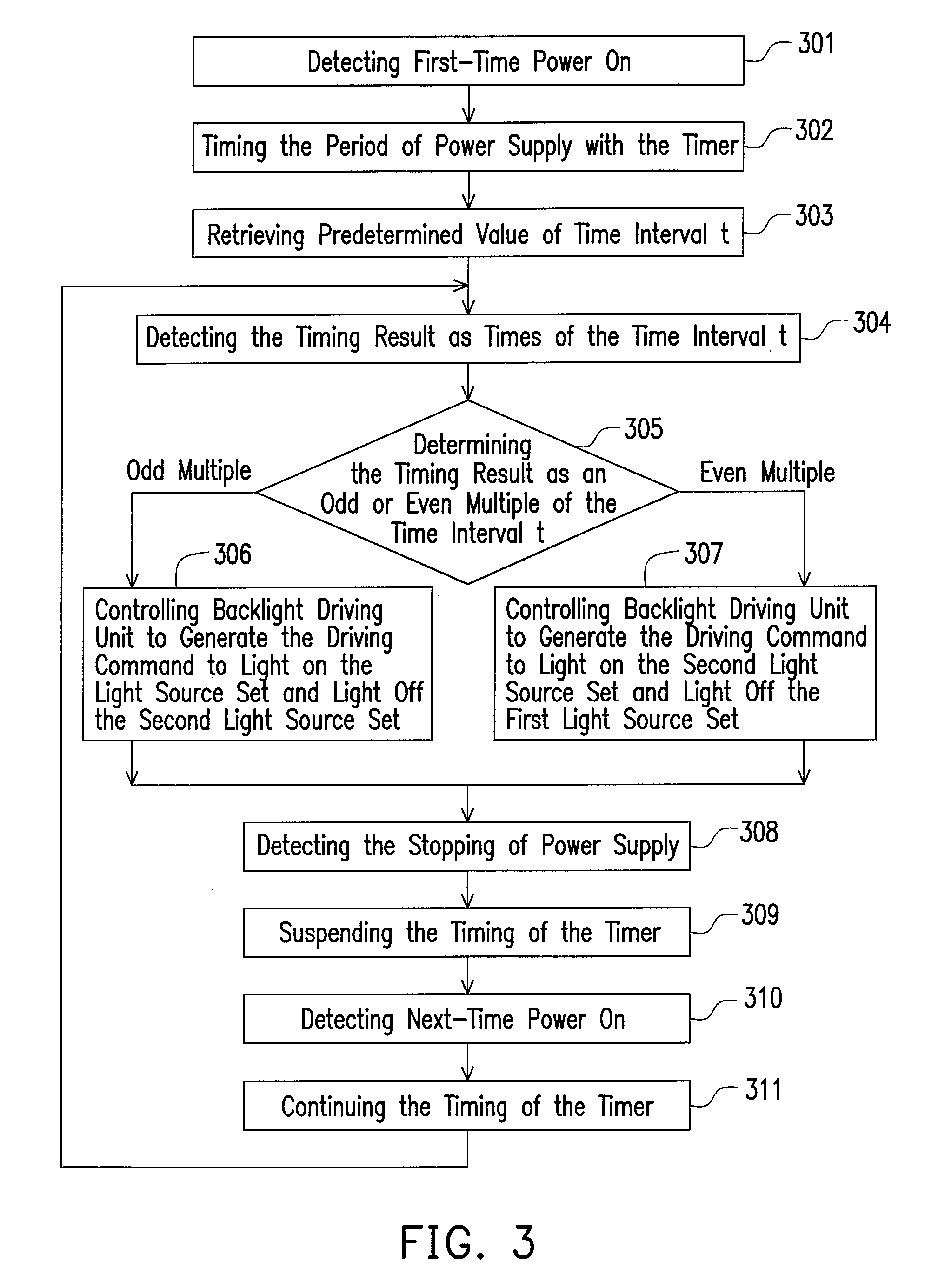
[0031]The backlight driving unit 11 is electrically connected to the power supply unit 10, the control unit 12, the first light source set 151 and the second light source set 152. The backlight driving unit 11 is controlled by the control unit 12 to generate a...

Example

The Second Embodiment

Driving Light Source Sets by Turns According to Times of Power on

[0037]Referring to FIG. 4, the components of a backlight module 120 according to the second embodiment of the present invention are similar to those of the first embodiment, which can be understood by referring to the description of FIG. 2 and is not repeated herein.

[0038]The difference between them is that the control unit 12 of the second embodiment further includes a counter 122 for counting the number of times of the power on as the timer 121 in the first embodiment. Then, the control unit 12 is to determine the counting result as an odd or even number, and to turn on / off the light source sets by turns, thus increasing the lifetime of the backlight module 120.

[0039]FIG. 5 is a flow chart showing a control method of the second embodiment. Referring to FIG. 5, there is described the steps of the control method as following. First, the control unit 12 detects the first-time power on (step 501). Ne...

Example

The Third Embodiment

Compensating Brightness Loss According to Decay period

[0041]Referring to FIG. 2 again, the components of a backlight module according to the third embodiment of the present invention are the same as those of the first embodiment, which can be understood by referring to the description of FIG. 2 and is not repeated herein.

[0042]However, the third embodiment of the present invention is to turn on / off the light source sets according to a predetermined decay period T. The decay period T defined herein is an estimation period that brightness of the light source sets decays from original to a predetermined degree. It should be noted that as different light sources are selected, the corresponding decay periods T are also different. An example is illustrated in the following.

[0043]FIG. 6 is a graph showing a brightness decay curve of the light source, in which the x-coordinate represents time with unit of year, and the y-coordinate represents brightness of the light sour...


PUM


Abstract

A backlight module including a control unit, a backlight driving unit, a first light source set, and a second light source set is provided. The backlight driving unit is controlled by the control unit to generate a driving command to light on/off the light source sets. Therefore, the first and second light source set can be lighted on or off by turns according to a predetermined value, e.g., a time interval, times of power on operations. Otherwise, the second light source set may be used to compensate a brightness loss of the first light sources set when the displaying brightness is not enough, so as to maintain the displaying brightness within a predetermined range. Therefore, a longer lifetime of the backlight module can be obtained.

Description

CROSS-REFERENCE TO RELATED APPLICATION[0001]This application claims the priority benefit of Taiwan application serial no. 95111501, filed Mar. 31, 2006. All disclosure of the Taiwan application is incorporated herein by reference.BACKGROUND OF THE INVENTION[0002]1. Field of the Invention[0003]The present invention relates to a backlight module, and particularly to a backlight module having a longer lifetime.[0004]2. Description of Related Art[0005]Referring to FIG. 1, a conventional backlight module 9 includes a plurality of light sources 91, a backlight driving unit 92 and a power supply unit 93. The light sources 91 are cold cathode fluorescent lamp (CCFL) tubes, and the backlight driving unit 92 is coupled between the power supply unit 93 and the light sources 91.[0006]The power supply unit 93 provides power and drives the light sources 91 in conjunction with the backlight driving unit 92. Then, the light emitted from the light sources 91 is projected onto a display panel (now sh...

Claims


Application Information

Patent Timeline
IPC IPC(8): G09G3/36
CPCG09G3/3406G09G2310/0237G09G2320/0653G09G2320/0626G09G2320/043
Inventor LIN, CHEN-HUNGKUO, TZU-SHOUCHENG, MING-HUI
Owner CORETRONIC
Why Eureka
Try Eureka