Exposure apparatus
a technology of exposure apparatus and liquid holding plate, which is applied in the direction of photosensitive materials, instruments, printers, etc., can solve the problems of degrading the exposure accuracy, difficult to perform highly accurate temperature adjustment, and affecting the exposure accuracy, so as to suppress the influence of the thermal deformation of the liquid holding plate, excellent exposure accuracy, and reduce deformation
- Summary
- Abstract
- Description
- Claims
- Application Information
AI Technical Summary
Benefits of technology
Problems solved by technology
Method used
Image

Examples
first embodiment
[0034](Arrangement of Immersion Exposure Apparatus)
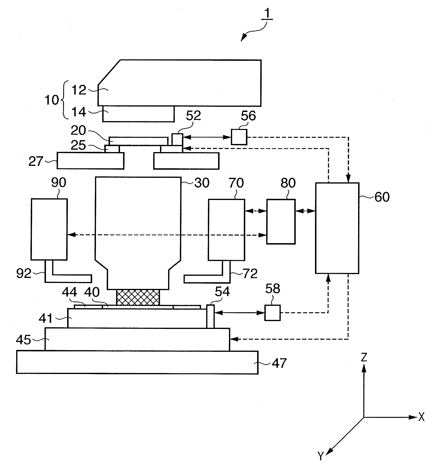
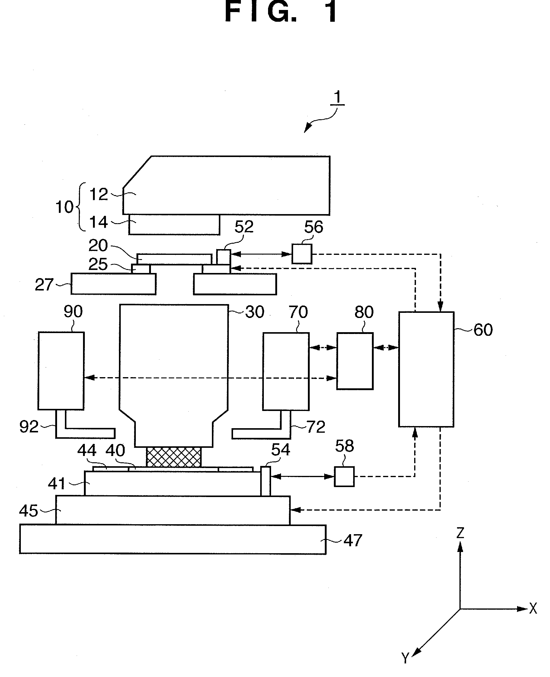
[0035]FIG. 1 is a view showing the arrangement of an immersion type exposure apparatus 1 (to be merely referred to as an “exposure apparatus” as well hereinafter) according to the first embodiment of the present invention.
[0036]The exposure apparatus 1 can expose a circuit pattern formed on a reticle 20 onto a wafer 40 by the step-and-scan scheme through a liquid (immersion liquid) LW supplied between the final surface of a projection optical system 30 on a side of a wafer 40 and the wafer 40. The “step-and-scan scheme” continuously scans the wafer 40 with respect to the reticle 20 to expose the reticle pattern onto the exposure area of the wafer, and steps the wafer to the next exposure area, when one-shot exposure ends, to expose it.
[0037]The present invention does not limit the exposure method to the step-and-scan scheme, but can also be applied to a “step-and-repeat scheme” liquid immersion type projection exposure apparatus whi...
second embodiment
[0078]The second embodiment of the present invention will be described with reference to FIGS. 5 and 6. The same portions as in the arrangement according to the first embodiment are denoted by the same reference numerals, and a repetitive description on the common arrangement is omitted.
[0079]FIG. 5 is a view showing the arrangement of a wafer 40, a liquid holding plate 154, and attaching members 53, which connect a top plate 41 of a wafer stage 45 to the liquid holding plate 154, in the X-Y plane. The liquid holding plate 154 according to this embodiment is different from the liquid holding plate 44 according to the first embodiment in that it comprises a plurality of members (a member 154A and a member 154B). The arrangement of liquid holding plate 154 will be described later in detail. FIG. 6 is an enlarged view of part of the arrangement in FIG. 5 seen from a side surface (X-Z plane).
[0080]The liquid holding plate 154 according to this embodiment is divided into a wafer peripher...
third embodiment
[0086]The third embodiment of the present invention will be described with reference to FIGS. 7 and 8. The same portions as in the arrangements according to the first and second embodiments are denoted by the same reference numerals, and a repetitive description on the common arrangement is omitted.
[0087]FIG. 7 is a view showing the arrangement of a wafer 40, a liquid holding plate 174, and attaching members 53, which connect a top plate 41 of a wafer stage 45 to the liquid holding plate 174, in the X-Y plane. The liquid holding plate 174 according to this embodiment is different from the liquid holding plate 154 according to the second embodiment in that a separating portion 51 is provided between a plurality of members (a member 174A and a member 174B). The arrangement of liquid holding plate 174 will be described later in detail. FIG. 8 is an enlarged view of part of the arrangement in FIG. 7 seen from a side surface (X-Z plane).
[0088]The liquid holding plate 174 according to thi...
PUM
 Abstract
Description
Claims
Application Information
 - Generate Ideas
- Intellectual Property
- Life Sciences
- Materials
- Tech Scout
- Unparalleled Data Quality
- Higher Quality Content
- 60% Fewer Hallucinations
Browse by: Latest US Patents, China's latest patents, Technical Efficacy Thesaurus, Application Domain, Technology Topic, Popular Technical Reports.
© 2025 PatSnap. All rights reserved.Legal|Privacy policy|Modern Slavery Act Transparency Statement|Sitemap|About US| Contact US: help@patsnap.com