
Wind-guiding cover

a wind-guiding cover and wind-guiding technology, which is applied in the direction of electrical apparatus casings/cabinets/drawers, instruments, cooling/ventilation/heating modifications, etc., can solve the problems of adversely affecting the heat dissipation operation adversely affecting the heat dissipation of the heat generating component, and not being subject to satisfactory heat dissipation, etc., to achieve satisfactory heat dissip

Inactive Publication Date: 2007-10-04
INVENTEC CORP
View PDF7 Cites 11 Cited by
  • Summary
  • Abstract
  • Description
  • Claims
  • Application Information

AI Technical Summary

Benefits of technology

[0008] In light of the above drawbacks in the prior art, an objective of the present invention is to provide a wind-guiding cover to improve a heat dissipating effect for a heat generating component of an electronic device.
[0009] Another objective of the present invention is to provide a wind-guiding cover that is easy to be assembled and disassembled to and from an electronic device.
[0011] A further objective of the present invention is to provide a wind-guiding cover to achieve a satisfactory heat dissipating effect for a heat generating component and an electronic component of an electronic device respectively and prevent interference therebetween.
[0014] By applying the wind-guiding cover of the present invention to the electronic device and through operation of the fan and a heat dissipating member of the electronic device, heat generated by electronic components of the electronic device and the heat generating component can be dissipated out of the electronic device. This can solve the problem in the prior art that a heat generating component cannot be subject to satisfactory heat dissipation and its heat dissipating operation is adversely affected as heat generated by the heat generating component and to be dissipated is undesirably drawn into a server by operation of a plurality of fans of the server. Therefore, the wind-guiding cover of the present invention can achieve a satisfactory heat dissipating effect for the electronic components and the heat generating component of the electronic device.
[0015] Moreover, the wind-guiding cover of the present invention can solve the other problems in the prior art, such as increase in the cost due to necessarily providing a fan in a conventional wind-guiding cover, unsatisfactory heat dissipation for the heat generating component (such as power supply) and the electronic components, and so on.

Problems solved by technology

Therefore, how to dissipate the heat satisfactorily for the electronic components and the heat generating components has become an issue to be solved at present.
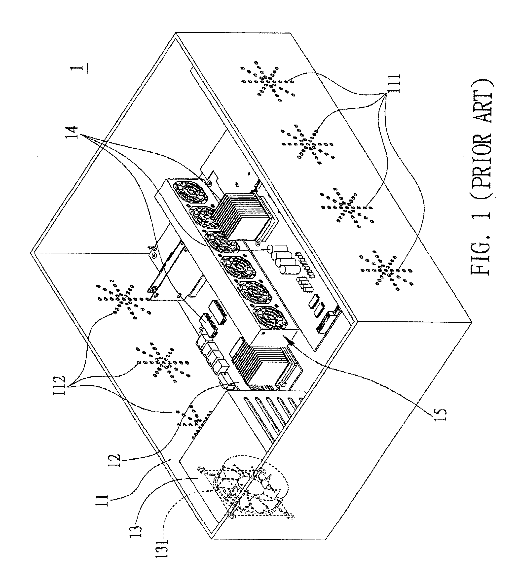
However, the plurality of fans 15 during operation would also draw the heat from the heat generating component 13, which is intended to be dissipated, into the server 1, thereby adversely affecting the heat dissipation operation for the heat generating component 13 and making the heat generating component 13 not subject to satisfactory heat dissipation.
Moreover, when more and more heat is introduced to the server 1, it may cause damage to the electronic components 14 and the heat generating component 13.
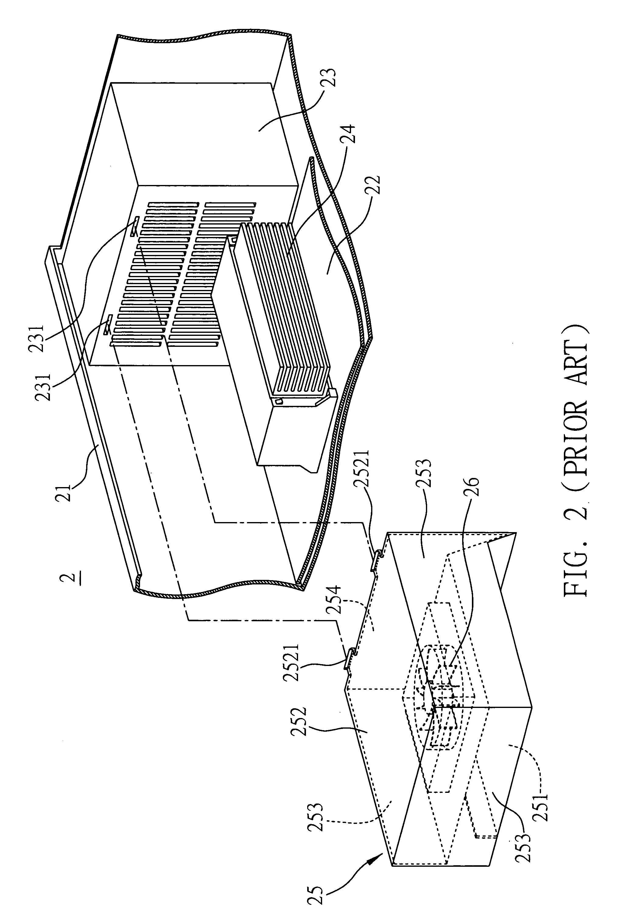
However, the above wind-guiding cover 25 must be provided with the fan 26 therein, which undesirably increases the cost.

Method used


Image

  • Wind-guiding cover
  • Wind-guiding cover
  • Wind-guiding cover

Examples


first preferred embodiment

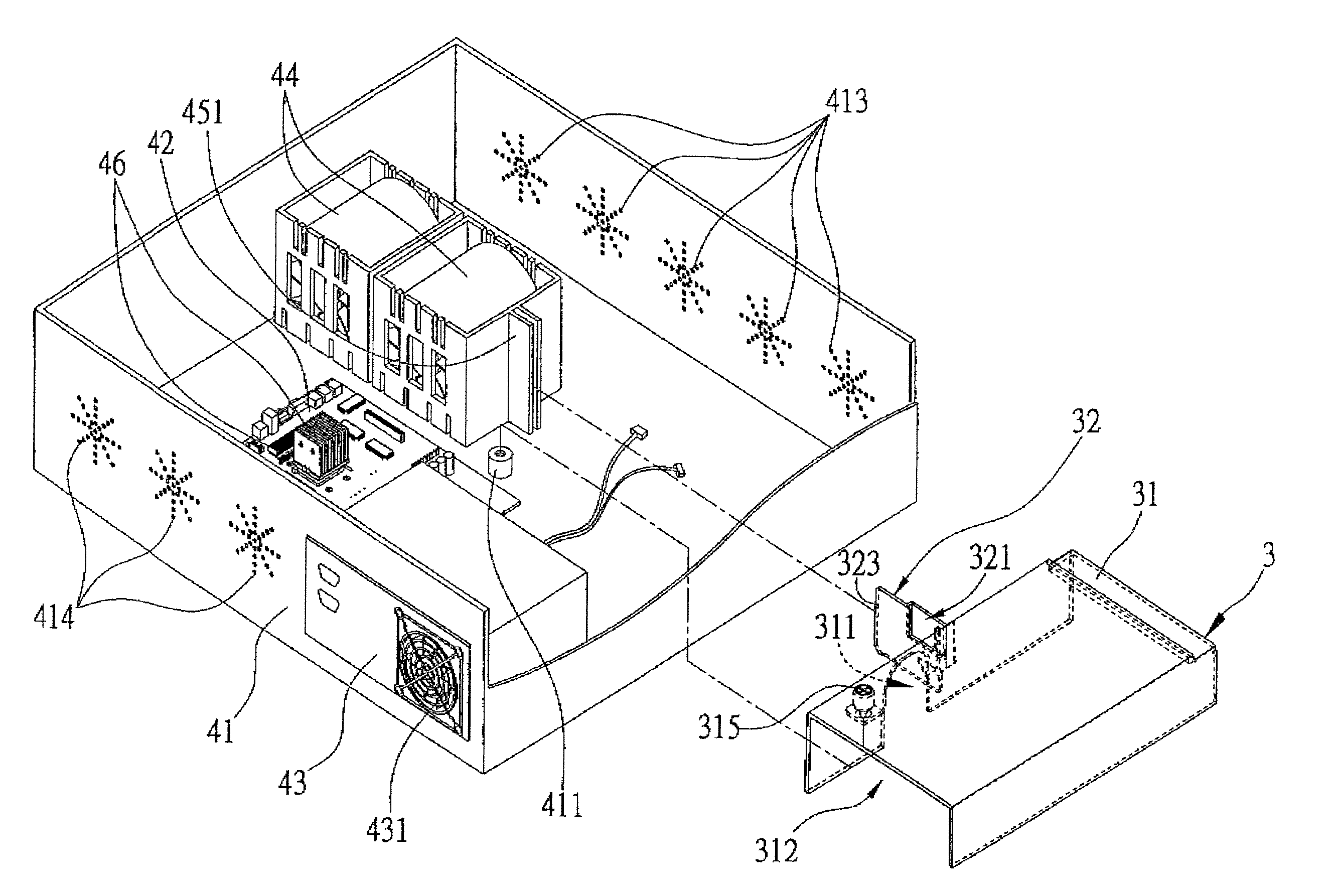
[0025] FIGS. 3 to 6 shows a wind-guiding cover 3 according to a first preferred embodiment of the present invention. As shown in FIG. 6, the wind-guiding cover 3 is mounted in an electronic device 41 having a heat generating component 43, a first coupling portion 411, a first positioning portion 451 and an air inlet 413, wherein the heat generating component 43 has a fan 431. The wind-guiding cover 3 comprises a main body 31 and a separator 32 connected to the main body 31.

[0026] It should be noted that the wind-guiding cover 3 in the following embodiments can be applied to the electronic device 41 such as a desktop computer, a laptop computer, a server or any other electronic device having a heat dissipating member (such as a fan) 44 and the heat generating component 43 (such as a power supply). Although the embodiments herein take the server for illustration, it is understood that the present invention is not limited to such arrangement. For the sake of simplicity, the drawings h...

second preferred embodiment

[0032]FIG. 7 illustrates the wind-guiding cover 3 according to a second preferred embodiment of the present invention, wherein same or similar components as compared with those of the first embodiment are denoted with same or similar reference numerals, and their detailed descriptions are omitted here for the same of brevity.

[0033] Primary differences between the second embodiment and the first embodiment are in that, as shown in FIG. 7, the electronic device 41 is provided with a mainboard 48 on which a plurality of expansion cards 47 are mounted, and the separator 32 comprises a window board 321 that can be removed to form a gap 322 on the separator 32, to allow cables 432 for wiring of the heat generating component 43 to pass through the gap 322 to be connected to the mainboard 48 so as to supply power to the mainboard 48, thereby providing an effect of accommodating the cables 432 and properly arranging the wiring.

[0034] Therefore, by applying the wind-guiding cover of the pre...


PUM


Abstract

A wind-guiding cover is provided, which is mounted in an electronic device having a heat generating component, a first coupling portion, a first positioning portion and an air inlet, wherein the heat generating component has a fan. The wind-guiding cover includes a main body and a separator. The main body is disposed between the heat generating component and the air inlet, and includes a channel for connecting the heat generating component to the air inlet, and a second coupling portion for being coupled to the first coupling portion, so as to allow the fan to directly introduce cooling air from the air inlet to the heat generating component to dissipate heat generated by the heat generating component. The separator is connected to a side of the main body and has a second positioning portion for being coupled to the first positioning portion.

Description

FIELD OF THE INVENTION [0001] The present invention relates to wind-guiding covers, and more particularly, to a wind-guiding cover applied to an electronic device. BACKGROUND OF THE INVENTION [0002] As the technology advances, electronic devices have become part of life for the modern people. An electronic device (for example a computer server) consists of many parts such as disk drive, power supply and mainboard, wherein the mainboard is provided with many electronic components thereon such as memory, IC component, central processing unit (CPU) and so on. With functionality of the electronic device being continuously enhanced, the number of the electronic components mounted in the electronic device is also increased. Accordingly, when the electronic device operates, more and more heat is generated by the electronic components and heat generating components of the electronic device. Therefore, how to dissipate the heat satisfactorily for the electronic components and the heat genera...

Claims


Application Information

Patent Timeline
Patent Type & Authority Applications(United States)
IPC IPC(8): H05K7/20
CPCH05K7/20727G06F1/20
Inventor CHANG, LIN-WEIHSIEH, CHI-KANG
Owner INVENTEC CORP
Learn More