

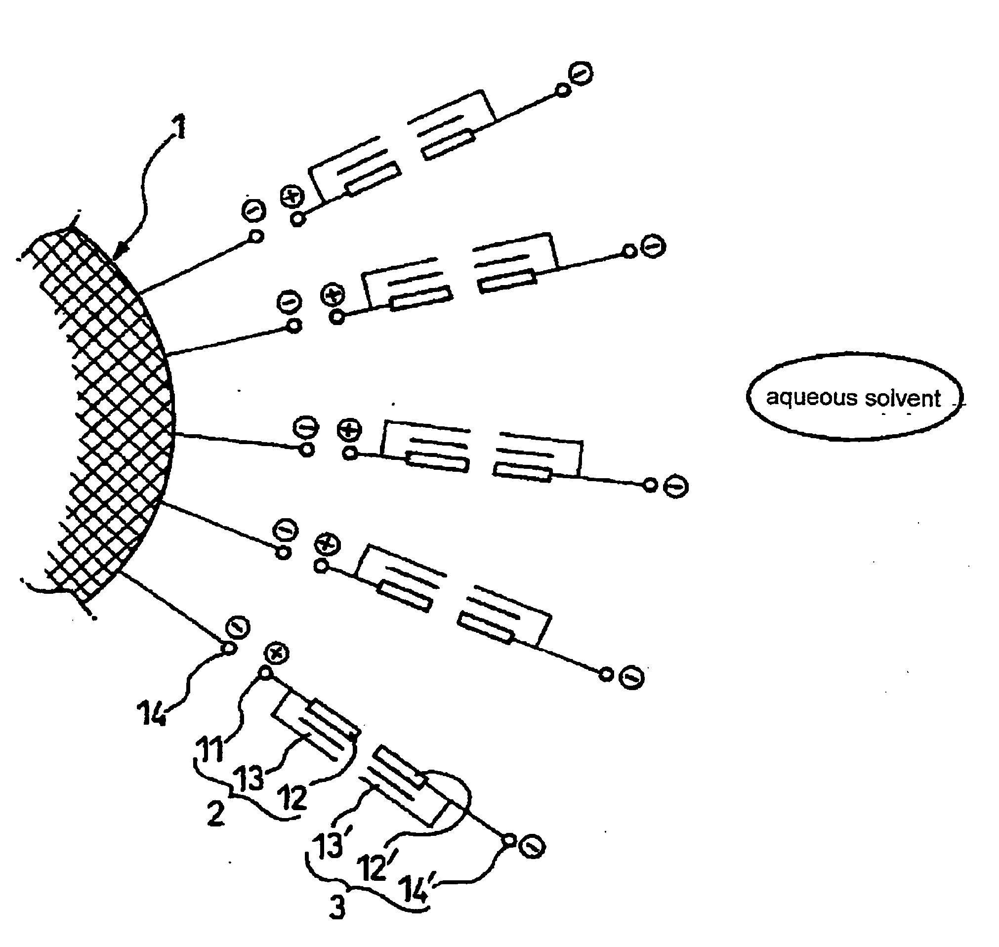
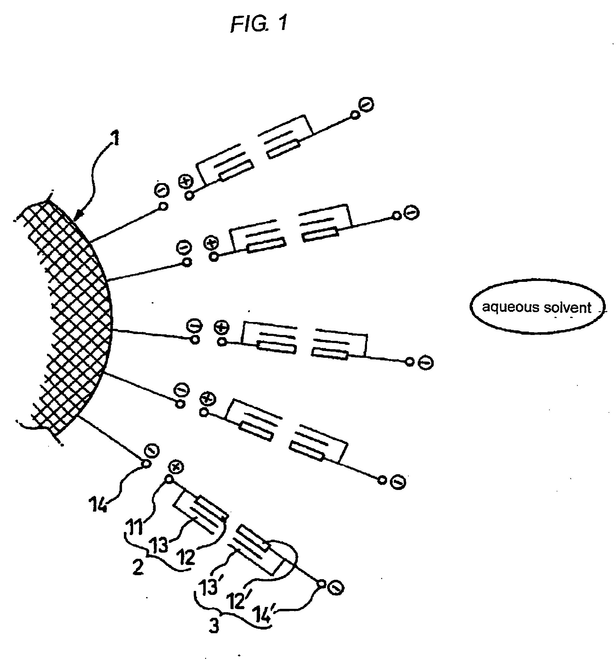
Microencapsulated particulate metal material, method for producing the same, and aqueous dispersion and ink jet ink using the same
a technology of microencapsulation and metal materials, which is applied in the direction of cellulosic plastic layered products, natural mineral layered products, transportation and packaging, etc., can solve the problems of reducing the adhesion of metal particles to the substrate surface, aggregation of metal particles, etc., and achieves the effect of improving the adhesion of metal particles to the surfa
- Summary
- Abstract
- Description
- Claims
- Application Information
AI Technical Summary
Benefits of technology
Problems solved by technology
Method used
Image

Examples
example 3
Formation of Conductive Films Using Ink Jet Ink
[0277] The fine silver particle containing ink jet ink 1 was ejected onto a glass substrate that had been subjected to a liquid repellency treatment at predetermined dot intervals using an ink jet apparatus to form conductive film lines. The dot interval was changed only by adjusting the ejection frequency, with the stage moving velocity kept constant. As the ink jet head, the head of a commercially available printer (product name “MJ930C”) was used. However, the ink suction portion of the head was made of plastic, and therefore the suction port was changed to a metal jig so that it would not be dissolved in the organic solvent.
[0278] The liquid repellency treatment of the substrate was conducted as follows. First, as a pre-treatment, the glass substrate was cleaned by irradiation of ultraviolet light having a wavelength of 172 nm with 10 mW for 10 minutes. Then, in order to form a liquid-repellent and self-organizing film on the enti...
example 4
Formation of Conductive Film Using Ink Jet Ink
[0283] After forming a self-organizing film in the method described in Example 3, the same ink and ink jet apparatus as those in Examples 3 were used to form conductive film lines on a substrate whose liquid repellency had been reduced by irradiation of ultraviolet light.
[0284] More specifically, after a self-organizing film was formed in the same manner as in Example 3, lines were formed on a substrate that had been irradiated with ultraviolet light with 10 mW / cm2 for 5 minutes. Since the amount of the self-organizing film removed was small, the substrate after the irradiation of ultraviolet light had a certain degree of liquid repellency, and the contact angle of the fine silver particle ink 1 on the substrate was approximately 30°. The diameter of the droplets on this substrate was 150 μm in the ejection with an ejection voltage of 20 V. When the line formation was performed by conducting ejection at a dot interval of 135 μm, that i...
PUM
| Property | Measurement | Unit |
|---|---|---|
| volume average particle size | aaaaa | aaaaa |
| glass transition temperature | aaaaa | aaaaa |
| aspect ratio | aaaaa | aaaaa |
Abstract
Description
Claims
Application Information