Ionizer and Static Elimination Method

Active Publication Date: 2010-02-25
KEYENCE
View PDF4 Cites 30 Cited by
  • Summary
  • Abstract
  • Description
  • Claims
  • Application Information

AI Technical Summary

Benefits of technology

[0029]In the fifth aspect of the present invention, the gas channel has the throat part for narrowing the gas channel such that the channel area gradually decreases. Therefore, the ratio of the atmospheric pressure to the gas pressure at the position where the channel area does not vary, the position being located forward of the throat part, becomes not more than 0.528. Moreover, the velocity of flow of the gas immediately after emission from the emission port exceeds the velocity of sound, and the gas pressure at the emission port is not less than the atmospheric pressure. Thus, it is possible to set the optimum expansion status or the under expansion status. In particular, the surface where the channel area is minimized (the throat surface) is defined near the emission port. Herein, the distance from the throat surface to the emission port is made approximate to 0 (zero) and the ratio of the channel area at the discharge port to the channel area at the throat surface is made approximate to 1. Thus, it is possible to set the optimum expansion status or the under expansion status even when the amount of flow of the gas is small.
[0030]In the sixth aspect of the present invention, the channel area is minimized at the emission port. Therefore, the emission port can be used as the throat part without the throat part provided on the midpoint position of the gas channel. Moreover, the ratio of the atmospheric pressure to the gas pressure at the position where the channel area does not vary, the position being located forward of the throat part, is not more than 0.528. As a result, the velocity of flow of the gas immediately after emission from the emission port exceeds the velocity of sound, and the gas pressure at the emission port becomes not less than the atmospheric pressure. Thus, it is possible to set the optimum expansion status or the under expansion status.
[0031]In the seventh aspect of the present invention, the ratio of the atmospheric pressure to the gas pressure at the position where the channel area does not vary, the position being located forward of the throat part, is not more than 0.528. As a result, the velocity of flow of the gas immediately after emission from the emission port exceeds the velocity of sound, and

Problems solved by technology

Since the air ions are electrically charged, foreign matters such as dust and dirt floating in the air are also prone to be electrically charged.
Consequently, the ambient foreign matters such as dust and dirt are prone to be attached to the discharge electrode.
Even when the ionizer is used in the clean room, there still remains a slight amount of foreign matters such as dust in the clean room.
Consequently, the electrically charged foreign matters are disadvantageously attached to a tip of the discharge electrode by a principle similar to the principle described above.
Moreover, the attached dust and the like gather in a cluster and fall on the clean room.
Consequently, there is a possibility that such dust and the like make it difficult to keep the environment of the clean room in a favorable state.
However, a satisfactory static elimination effect can not b

Method used


Image

  • Ionizer and Static Elimination Method
  • Ionizer and Static Elimination Method
  • Ionizer and Static Elimination Method

Examples


first embodiment

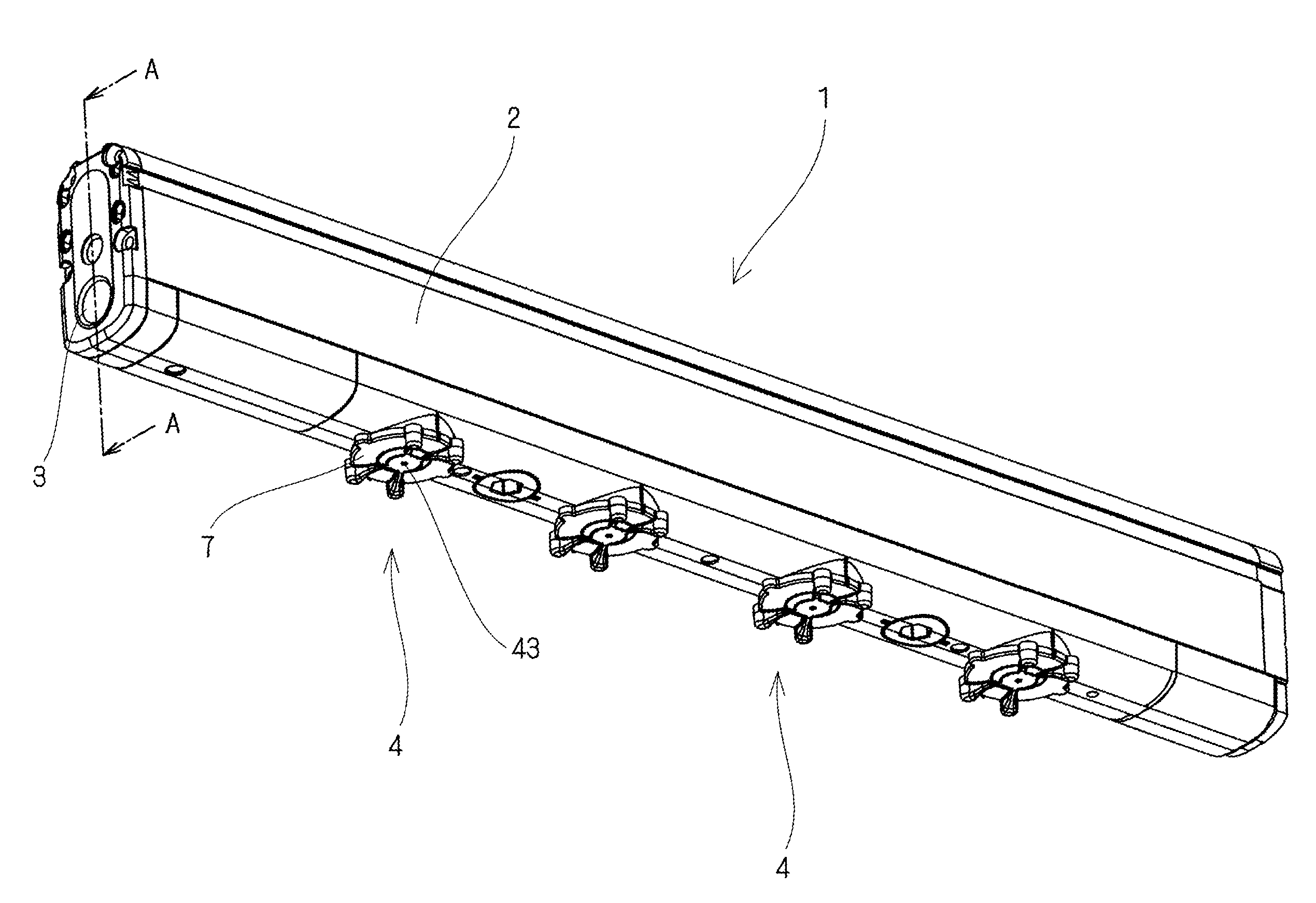
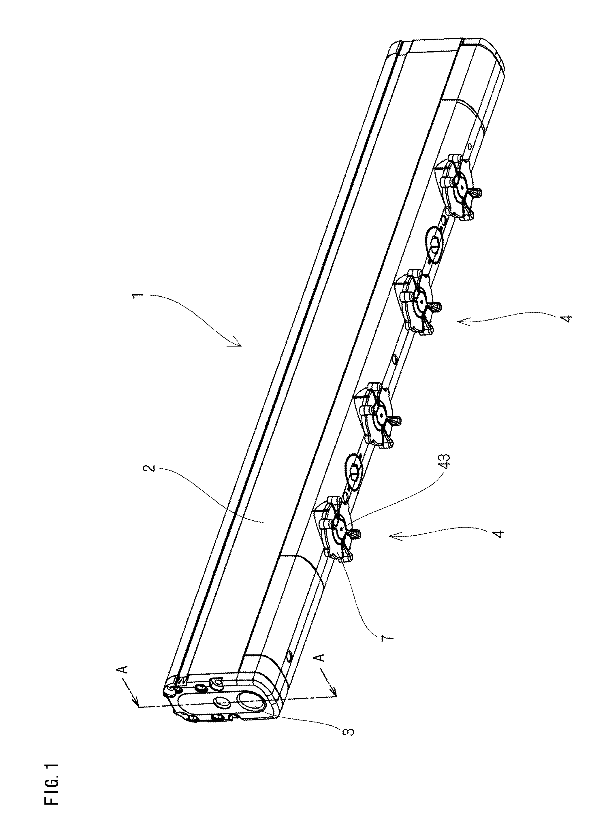
[0060]FIG. 1 shows a perspective view of a schematic configuration of an ionizer according to a first embodiment of the present invention. As shown in FIG. 1, the ionizer 1 according to the first embodiment is of a so-called bar type and includes a main body casing 2 and a plurality (four in the example shown in FIG. 1) of nozzles 4. The main body casing 2 is in a substantially rectangular parallelepiped shape and has rounded longitudinal corners. The plurality of nozzles 4 are provided on one surface of the main body casing 2 in a longitudinal direction of the main body casing 2 at predetermined intervals. Each nozzle 4 is embedded in the main body casing 2 except a disc-shaped portion 7 having an emission port 43 for emitting supplied gas together with ions ejected from a discharge electrode (to be described later). A gas supplying port 3 is provided on a longitudinal end surface of the main body casing 2 and supplies, to each nozzle 4, clean gas obtained by filtrating air, nitrog...

second embodiment

[0107]An ionizer 1 according to a second embodiment of the present invention is similar in configuration to the ionizer 1 according to the first embodiment. Therefore, elements having identical or similar configurations or functions are denoted by identical or similar reference symbols, and detailed description thereof will not be given here. In the second embodiment, a nozzle 204 is different in shape from the nozzle 4 according to the first embodiment. FIG. 22A shows a perspective view of the nozzle 204 of the ionizer 1 according to the second embodiment. FIG. 22B shows a sectional view taken along a line F-F in the perspective view shown in FIG. 22A. FIG. 22C shows an enlarged view of a portion G shown in FIG. 22B.

[0108]As shown in FIGS. 22A to 22C, the nozzle 204 according to the second embodiment includes a discharge electrode 41, a gas channel 42, an emission port 43, a gas supply port 44, and a throat part 45 serving as a throat surface 451. These components are similar in fu...


PUM


Abstract

The ionizer includes a nozzle having a discharge electrode for inducing corona discharge by application of high voltage to eject ions, an emission port for emitting supplied gas together with the ejected ions, and a gas channel for guiding supplied gas to the emission port. Herein, a velocity of flow of the gas immediately after emission from the emission port exceeds a velocity of sound, and a gas pressure at the emission port is not less than an atmospheric pressure. The gas channel has a throat part for narrowing the gas channel such that a channel area gradually decreases, and a ratio of the atmospheric pressure to a gas pressure at a position where the channel area does not vary, the position being located forward of the throat part, is not more than 0.528.

Description

CROSS-REFERENCE TO RELATED APPLICATIONS[0001]The present application claims foreign priority based on Japanese Patent Application No. 2008-210735, filed Aug. 19, 2008, the contents of which is incorporated herein by reference.BACKGROUND OF THE INVENTION[0002]1. Field of the Invention[0003]The present invention relates to an ionizer and a static elimination method for ionizing gas with ions ejected from a discharge electrode and bringing the ionized gas into contact with a target of static elimination in order to eliminate static electricity from the target.[0004]2. Description of the Related Art[0005]In a clean room and the like, conventionally, an ionizer has been used for preventing air from being electrically charged or eliminating static electricity from a target of static elimination. Herein, a discharge electrode induces corona discharge by application of high voltage to generate air ions. The generated air ions are brought into contact with a target of static elimination and ...

Claims


Application Information

Patent Timeline
IPC IPC(8): H01J27/00
CPCH01T23/00H01T19/04
Inventor FUJITA, TSUKASATOKITA, YUUKI
Owner KEYENCE
Why Eureka
Try Eureka