
Rotation device, method for controlling rotation of a driving source, computer readible medium and image forming apparatus including the rotation device

a technology of rotating devices and driving sources, which is applied in the direction of control systems, electrographic process apparatus, instruments, etc., can solve the problems of fluctuation of rotation speed, and deterioration of image quality, so as to reduce the rotation speed

Active Publication Date: 2007-10-04
RICOH KK
View PDF6 Cites 23 Cited by
  • Summary
  • Abstract
  • Description
  • Claims
  • Application Information

AI Technical Summary

Benefits of technology

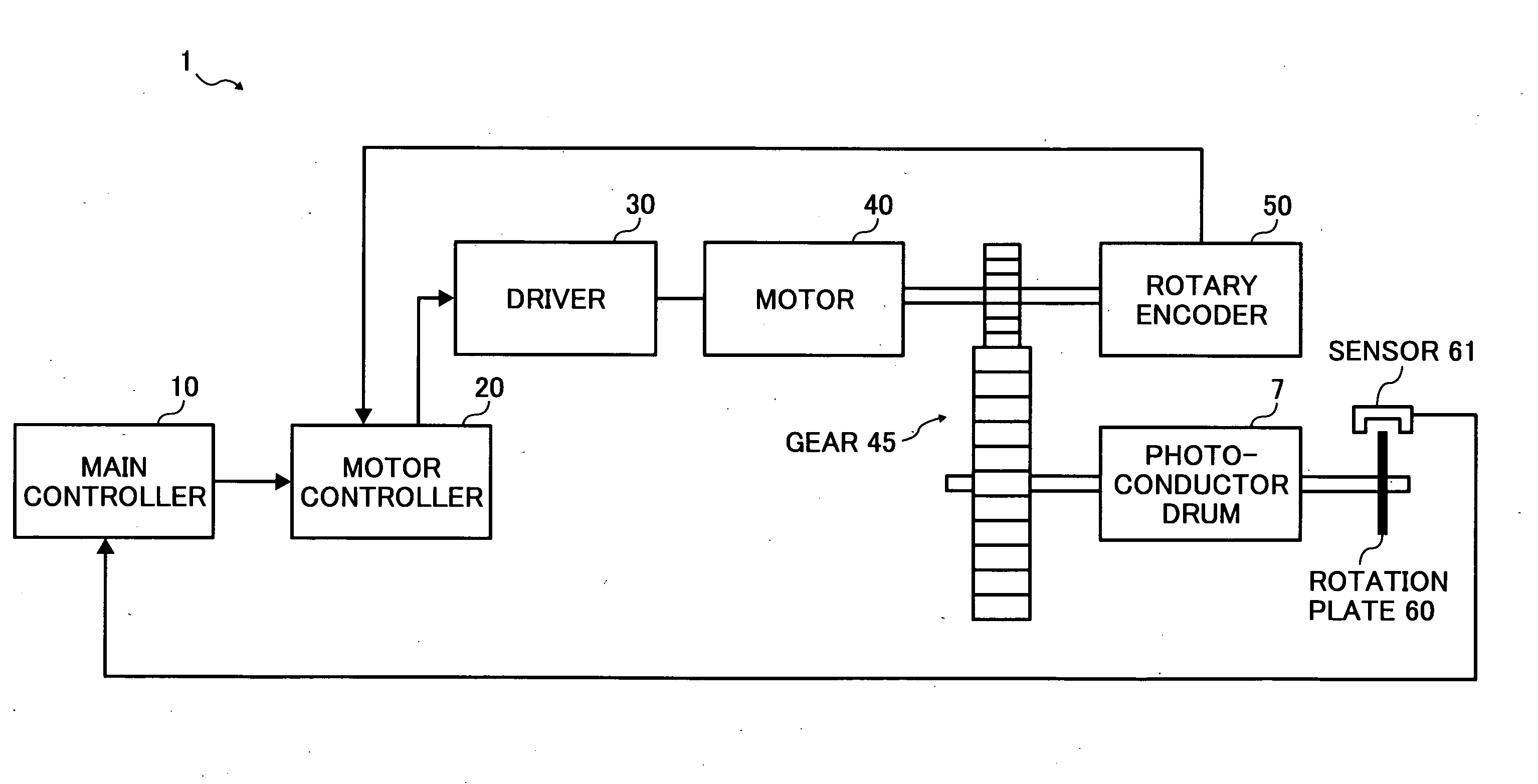
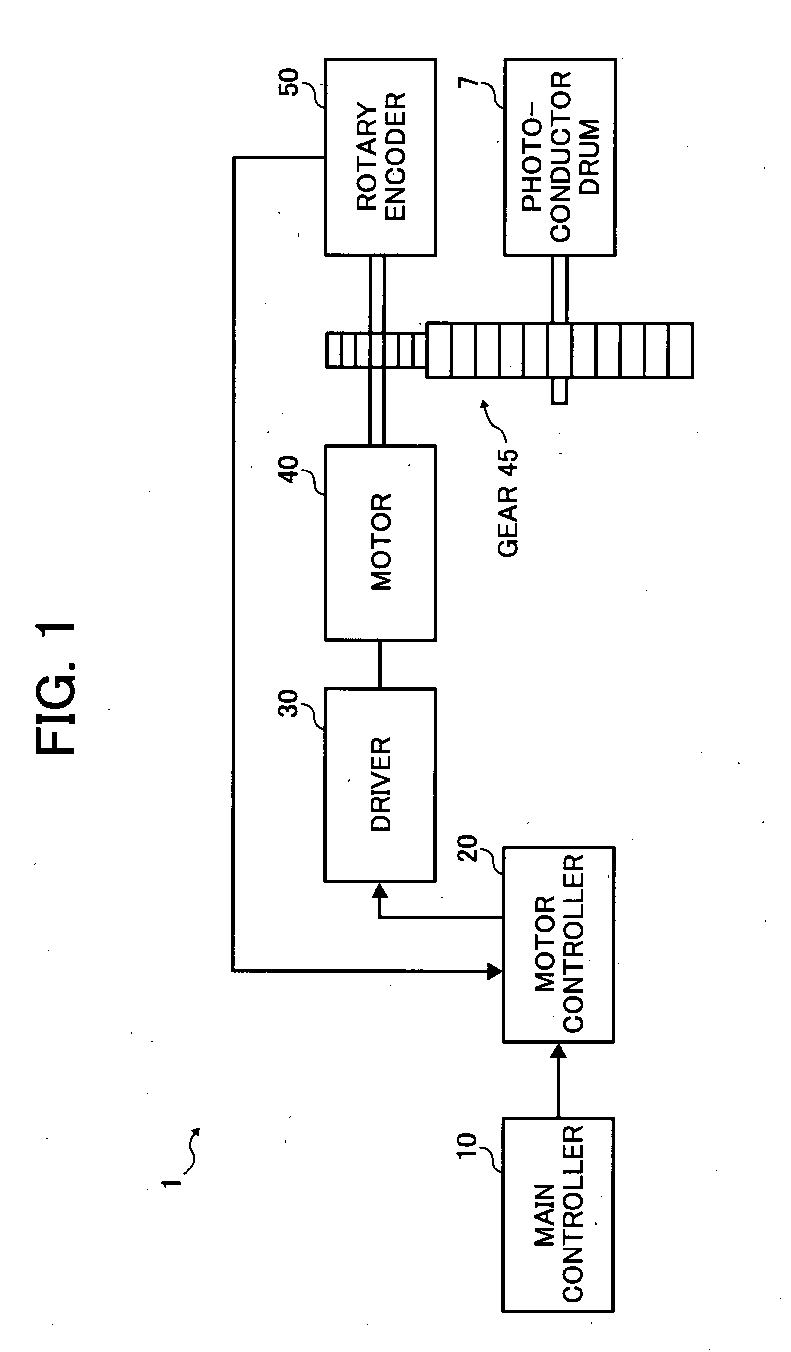
[0011] According to at least one example embodiment of the invention, a rotation device includes a rotation member, a rotation driving source, a transmission mechanism, a rotation pulse generation mechanism, a target value arrangement mechanism, a correction value computation mechanism, and a control mechanism. The rotation driving source is capable of controlling rotation speed t

Problems solved by technology

When the rotation speed of the photoconductor drum (i.e., sub-scanning speed) fluctuates, the positions of the main-scanning lines vary, resulting in deterioration of image quality.
Thus, when the sub-scanning speed fluctuates, image quality deteriorates.
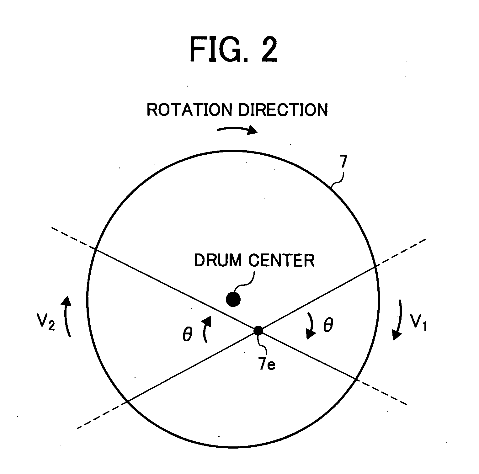
However, even when the motor rotates at a constant speed, the photoconductor causes the rotation speed fluctuation resulting from eccentricity of each rotation axis.

Method used


Image

  • Rotation device, method for controlling rotation of a driving source, computer readible medium and image forming apparatus including the rotation device
  • Rotation device, method for controlling rotation of a driving source, computer readible medium and image forming apparatus including the rotation device
  • Rotation device, method for controlling rotation of a driving source, computer readible medium and image forming apparatus including the rotation device

Examples


Embodiment Construction

[0038] It will be understood that if an element or layer is referred to as being “on”, “against”, “connected to” or “coupled to” another element or layer, then it can be directly on, against, connected or coupled to the other element or layer, or intervening elements or layers may be present. In contrast, if an element is referred to as being “directly on”, “directly connected to” or “directly coupled to” another element or layer, then there are no intervening elements or layers present. Like numbers referred to like elements throughout. As used herein, the term “and / or” includes any and all combinations of one or more of the associated listed items.

[0039] Spatially relative terms, such as “beneath”, “below”, “lower”, “above”, “upper” and the like may be used herein for ease of description to describe one element or feature's relationship to another element(s) or feature(s) as illustrated in the figures. It will be understood that the spatially relative terms are intended to encomp...


PUM


Abstract

A rotation device includes a rotation member, rotation driving source, transmission mechanism, rotation pulse generation mechanism, target value arrangement mechanism, correction value computation mechanism, and control mechanism. The transmission mechanism decreases the rotation speed at a non-integer gear ratio. The target value arrangement mechanism includes a rotation unevenness provision mechanism to impart a plurality of kinds of sine-wave unevenness to the rotation speed target value. The correction value computation mechanism determines the correction value to adjust rotation fluctuation caused by a rotation axis eccentricity component of the rotation driving source and at least one noise component having a cycle relationship with a rotation cycle of the rotation member based on a time interval of a pulse train generated every rotation of the rotation member by the rotation pulse generation mechanism when the plurality of kinds of the rotation unevenness are imparted to the rotation speed target value.

Description

PRIORITY STATEMENT [0001] This patent application is based on Japanese patent application No. 2006-076713, filed on Mar. 20, 2006 in the Japan Patent Office, the entire contents of which are hereby incorporated herein by reference. BACKGROUND [0002] 1. Field [0003] Example embodiments of the present application generally relate to a rotation device to control a rotation driving source such as motors, and to a rotation controlling method, a computer readable medium including a rotation controlling program and an image forming apparatus including the rotation device. [0004] 2. Description of the Related Art [0005] Recently, rotation devices for rotating a rotation member, which have a motor and a transmission mechanism to transmit rotation of the motor to the rotation member, are used to various fields, and are demanded to increase accuracy thereof. For example, image forming apparatuses such as printers, copiers, facsimile, etc. employing an electrophotographic method to form a toner...

Claims


Application Information

Patent Timeline
IPC IPC(8): G03G15/00G03G21/00G03G21/14H02P29/00
CPCG03G15/757G03G15/5008
Inventor WATAHIKI, TATSUYA
Owner RICOH KK
Learn More