

Electric compressor
- Summary
- Abstract
- Description
- Claims
- Application Information
AI Technical Summary
Benefits of technology
Problems solved by technology
Method used
Image

Examples
embodiment 1
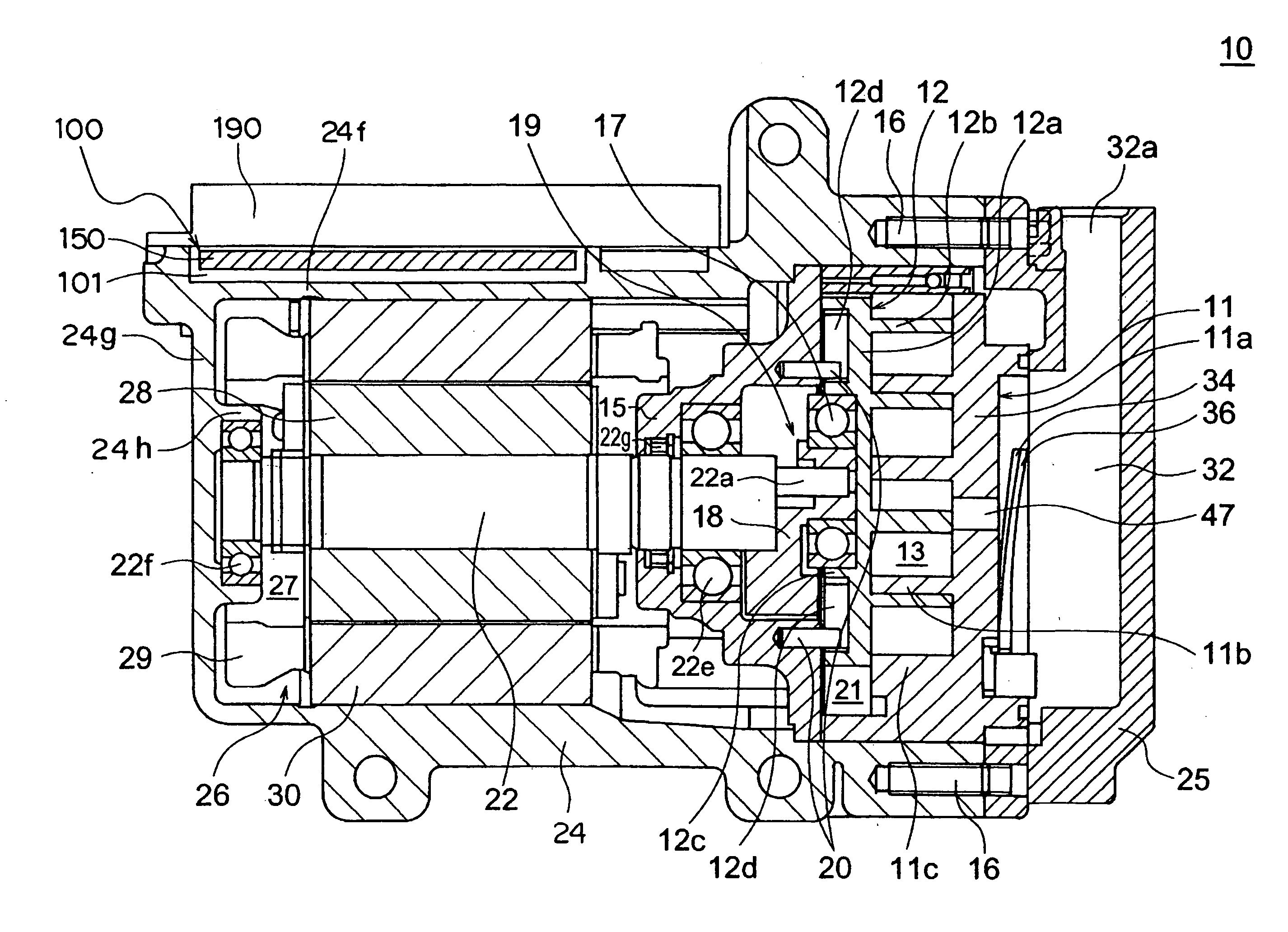
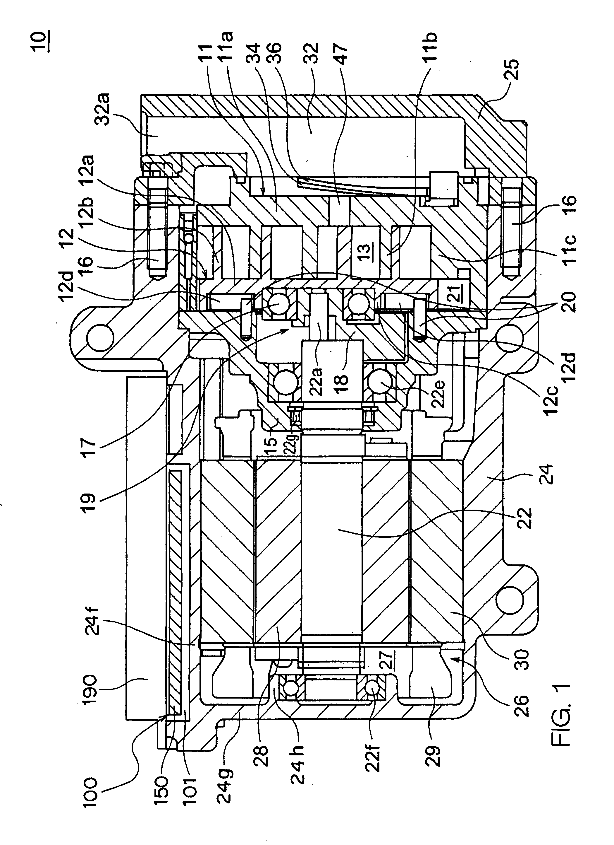
[0022]FIG. 1 illustrates an electric compressor 10 according to Embodiment 1 of the present invention.
[0023] The electric compressor 10 includes a first housing 24 and a second housing 25. The first housing 24 and the second housing 25 are locked to each other by bolts 16. The first housing 24 has a tubular shape with a closed bottom, including a tubular portion 24f and a bottom portion 24g, and the bottom portion 24g is provided with a shaft supporting portion 24h having a cylindrical shape.
[0024] Note that, in FIG. 1, the right side of the figure, namely, the second housing 25 side is defined as a front side, and the left side of the figure, namely, the bottom portion 24g side of the first housing24 is defined as a rear side.
[0025] The electric compressor 10 includes a fixed scroll 11, a rotary scroll 12 and a compression chamber 13 constructed of the fixed scroll 11 and the rotary scroll 12. The fixed scroll 11 includes a disc-like fixed base 11a, a spiral fixed lap 11b which ...
embodiment 2
[0084] Embodiment 2 has a structure in which the structure of the substrate 110 of Embodiment 1 is modified in the areas surrounding the connecting portion 112 as illustrated in FIG. 6.
[0085]FIGS. 6 and 7 illustrate the structure of an inverter assembly 200 used in the electrical compressor according to Embodiment 2 of the present invention. FIG. 6 illustrates a method of assembling the inverter assembly 200, and FIG. 7 illustrates an assembled state of the inverter assembly 200. Screws are used for assembling the inverter assembly 200, but the illustration of the screws is omitted. Note that, in Embodiment 2, the same reference symbols as used in FIGS. 1 to 5 of Embodiment 1 refer to the same or similar constructional elements, so the detailed descriptions thereof are omitted.
[0086] Hereinafter, description will be made of the points different from Embodiment 1 of the present invention.
[0087] As illustrated in FIG. 6, a substrate 210 includes slits 214 corresponding to respectiv...
embodiment 3
[0099] In Embodiment 3, the method of mounting the capacitor assembly 120 and other points in Embodiment 1 are modified.
[0100]FIG. 8 illustrates the structure including the inverter assembly 300 used in the electric compressor according to Embodiment 3. Note that, in Embodiment 3, the same reference symbols as used in FIGS. 1 to 5 of Embodiment 1 are for the same or similar constructional elements, so the detailed descriptions thereof are omitted.
[0101] Hereinafter, description will be made of the points different from Embodiment 2 of the present invention.
[0102] Provided to a base 350 is a receiving portion 352 formed integrally with the base 350 and covering a part of an exterior surface of a capacitor assembly 320. The receiving portion 352 and the surface on the base 350 side and the lower surface of the capacitor assembly 320 are fixed to each other by potting processing using a resinous adhesive 321.
[0103] Screws 360 are used for fixing the substrate 310 onto the base 350....
PUM
 Abstract
Description
Claims
Application Information