Tether member connecting a knee brace to a boot

a knee brace and tethering technology, applied in the field of tethering members, can solve the problems of knee injury, knee injury, prone to injury, etc., and achieve the effect of reducing the strain on the knee ligaments and reducing the chance of injury

Inactive Publication Date: 2007-10-04
ASTERISK ASTERISK
View PDF16 Cites 3 Cited by
  • Summary
  • Abstract
  • Description
  • Claims
  • Application Information

AI Technical Summary

Benefits of technology

[0013]It is contemplated that the tether member connects the knee brace and foot member to limit one from rotating independent from the other so as to mitigate the chance of injury. As such, the upper leg and lower leg of the user rotate together, thereby lessening the strain applied to the knee ligaments.

Problems solved by technology

The knee joint is one of the body's most intricate and exposed joints, thereby making it very prone to injury.
In addition, a knee injury may be caused when cartilage located within the knee joint becomes pinched between the bones and tears.
For that reason, sports related activities are one of the leading causes of injury to the knee.
Motocross is a very physically demanding sport that places a lot of stress on a rider's knees.
During a race, the rider is subjected to bumps from the other riders as well as hard landings, which may toss the rider off his bike.
Rough landings and accidents may place a lot of stress on a motocross rider's knee ligaments.
Although motocross riders may injure their ligaments due to forces directly applied to the knee joint, as described above, the riders are also prone to ligament tears due to pivoting activity, which a knee brace alone may not prevent.
If the rotation of the foot is severe, the knee ligaments will overextend or tear.
On some occasions, the rider's toe catches the dirt causing the rider's foot to rotate independently from the knee joint, imparting a strain on the rider's knee ligaments, specifically the ACL.
Most traditional knee braces will not mitigate the strain applied to the ligaments when the foot rotates independently from the knee joint.
A knee brace can prevent lateral motion, as well as forward and backward motion of the knee joint, however, most knee braces are not designed to effectively protect the ligaments from rotation.

Method used


Image

  • Tether member connecting a knee brace to a boot
  • Tether member connecting a knee brace to a boot
  • Tether member connecting a knee brace to a boot

Examples


Embodiment Construction

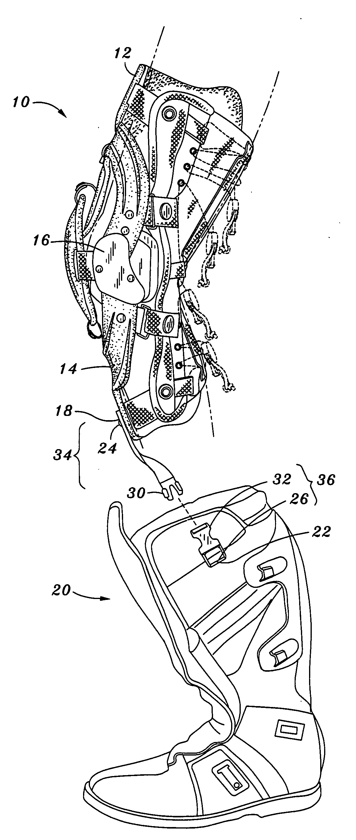
[0026]The ligaments holding a knee joint together are capable of withstanding a minimal level of tension. Knee ligaments may be placed in tension when a person's foot rotates independently from the corresponding knee joint. If the foot rotates independently from the knee joint to a point where the knee ligaments begin to overextend, the rotation of the foot has exceeded a maximum foot range of rotation. The present invention is a device which limits independent rotation of the foot relative to the knee joint to prevent rotation beyond the maximum foot range of rotation.

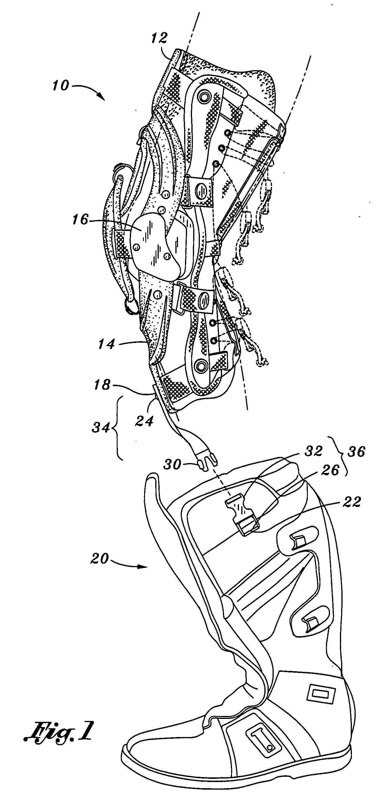
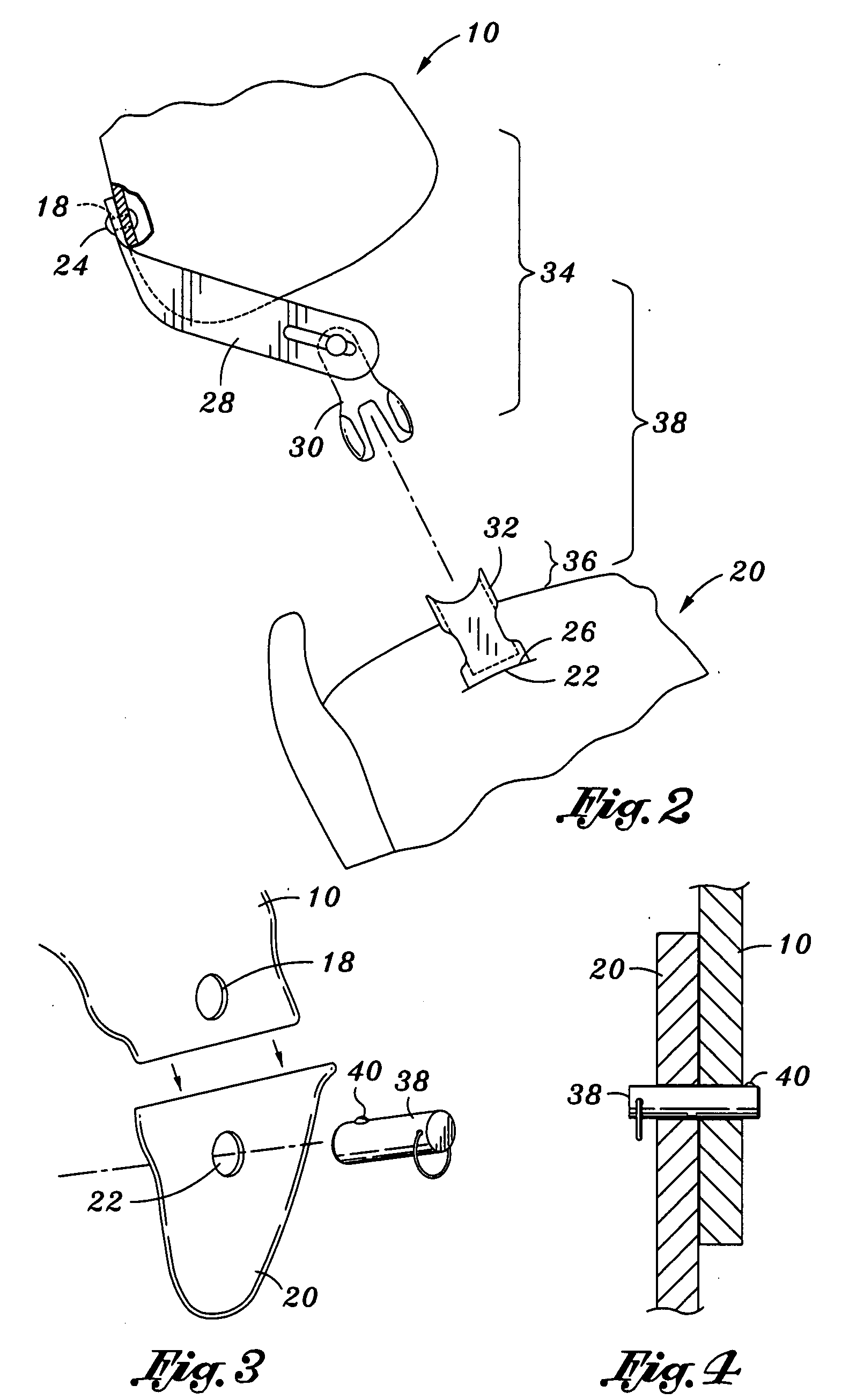
[0027]Referring to FIG. 1, there is provided a device for protecting ligaments in a knee joint of a user. The device includes a knee brace 10 positionable about a user's knee joint. The knee brace 10 comprises an upper frame member 12, a lower frame member 14, and a joint member 16 pivotally connected to the upper and lower frame members 12, 14. The upper frame member 12 further includes a brace connection point 18. T...


PUM


Abstract

The invention provides a device for protecting ligaments in a knee joint of a user. The device includes a knee brace positionable about a knee joint of a user and a foot member wearable on a foot of a user. Additionally, the device includes a flexible tether member including a first coupling element coupled to the knee brace and a second coupling element coupled to the foot member. The foot member and knee brace are attachable and detachable via the first and second coupling elements. The flexible tether member is adjustable in length to dispose the flexible tether member in tension at least in a portion of a maximum foot range of rotation, where the maximum foot range of rotation of the user's foot relative to the knee joint causes hyperextension of a knee ligament.

Description

CROSS-REFERENCE TO RELATED APPLICATIONS[0001]This application is a continuation-in-part of U.S. patent application Ser. No. 11 / 396,886 filed Apr. 3, 2006.STATEMENT RE: FEDERALLY SPONSORED RESEARCH / DEVELOPMENT[0002]Not ApplicableBACKGROUND[0003]1. Field of Invention[0004]This invention relates in general to a device for protecting the ligaments in a knee joint. Specifically, a knee brace and boot are attachable and detachable via a tether member. The tether member restricts the rotation of the knee brace relative to the boot in order to protect a user from overextending his knee ligaments.[0005]2. Description[0006]The knee joint is one of the body's most intricate and exposed joints, thereby making it very prone to injury. The knee joint is the connection between the femur, tibia, and fibula, which are stabilized by four ligaments. Two collateral ligaments located on the outside of the knee control the lateral motion of the knee. The anterior cruciate ligament (ACL) and posterior cru...

Claims


Application Information

Patent Timeline
Patent Type & Authority Applications(United States)
IPC IPC(8): A61F5/00
CPCA61F5/0123A61F2005/0165
Inventor CASTILLO, DAVIDCASTILLO, JAMES
Owner ASTERISK ASTERISK
Why Eureka
Try Eureka