Variable angle fixture, kit and method of presetting a nail assembly

a nail assembly and variable angle technology, applied in the field of orthopaedics, can solve the problems of complex devastating fractures, femur and tibia frequently fractures, trauma to long bones, etc., and achieve the effects of reducing the inventory of nail assemblies, and reducing the inventory of intramedullary nails

Inactive Publication Date: 2007-10-04
DEPUY PROD INC
View PDF10 Cites 36 Cited by
  • Summary
  • Abstract
  • Description
  • Claims
  • Application Information

AI Technical Summary

Benefits of technology

[0039] The technical advantages of the present invention include the ability to reduce inventory of intramedullary nails at a hospital or at a manufacturer's facility. For example, according to yet another aspect of the present invention, an intramedullary nail assembly is provided including a nail defining an aperture and a bushing fitted in the nail and adapted to be positioned in a plurality of positions. The nail assembly further includes a screw that may be positioned in the bushing to provide for a nail assembly with a plurality of angular relationships with respect to the nail.
[0040] Thus, the present invention provides for an intramedullary nail that includes a screw that may be positioned at various angular positions. By providing the nail assembly with a screw that may be positioned at various angular positions, an individual nail assembly is not necessary for each particular angular position or range of angular positions, thereby reducing inventory. Thus, the present invention provides for reduced inventory of nail assemblies.
[0041] The technical advantages of the present invention include the ability to provide a femoral intramedullary nail with a screw that may be positioned in the ideal angular position in the neck of the femur. For example, according to another aspect of the present invention, an intramedullary nail assembly is provided with a nail, including an opening and a bushing fitte...

Problems solved by technology

These long bones are particularly exposed to trauma from accidents, and as such often are fractured during such trauma and may be subject to complex devastating fractures.
Automobile accidents, for instance, are a common cause of trauma to long bones.
In part...

Method used


Image

  • Variable angle fixture, kit and method of presetting a nail assembly
  • Variable angle fixture, kit and method of presetting a nail assembly
  • Variable angle fixture, kit and method of presetting a nail assembly

Examples


Embodiment Construction

[0127] Embodiments of the present invention and the advantages thereof are best understood by referring to the following descriptions and drawings, wherein like numerals are used for like and corresponding parts of the drawings.

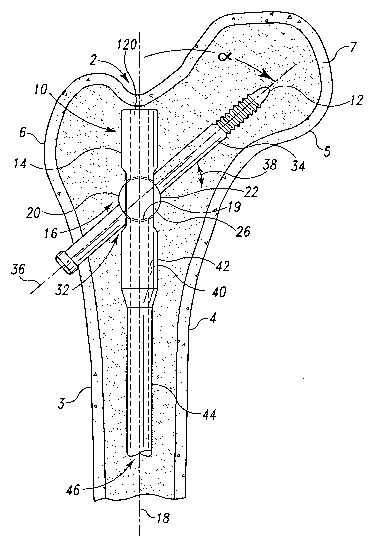
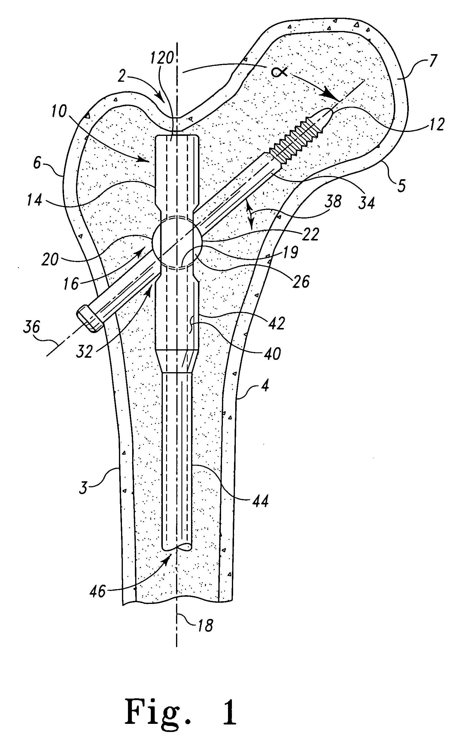
[0128] According to the present invention and referring now to FIG. 1, an intramedullary nail assembly 10 is shown for use in the intramedullary canal 2 of a long bone 4. The long bone 4 may be any long bone of the body, for example, a femur, tibia, or a humerus.

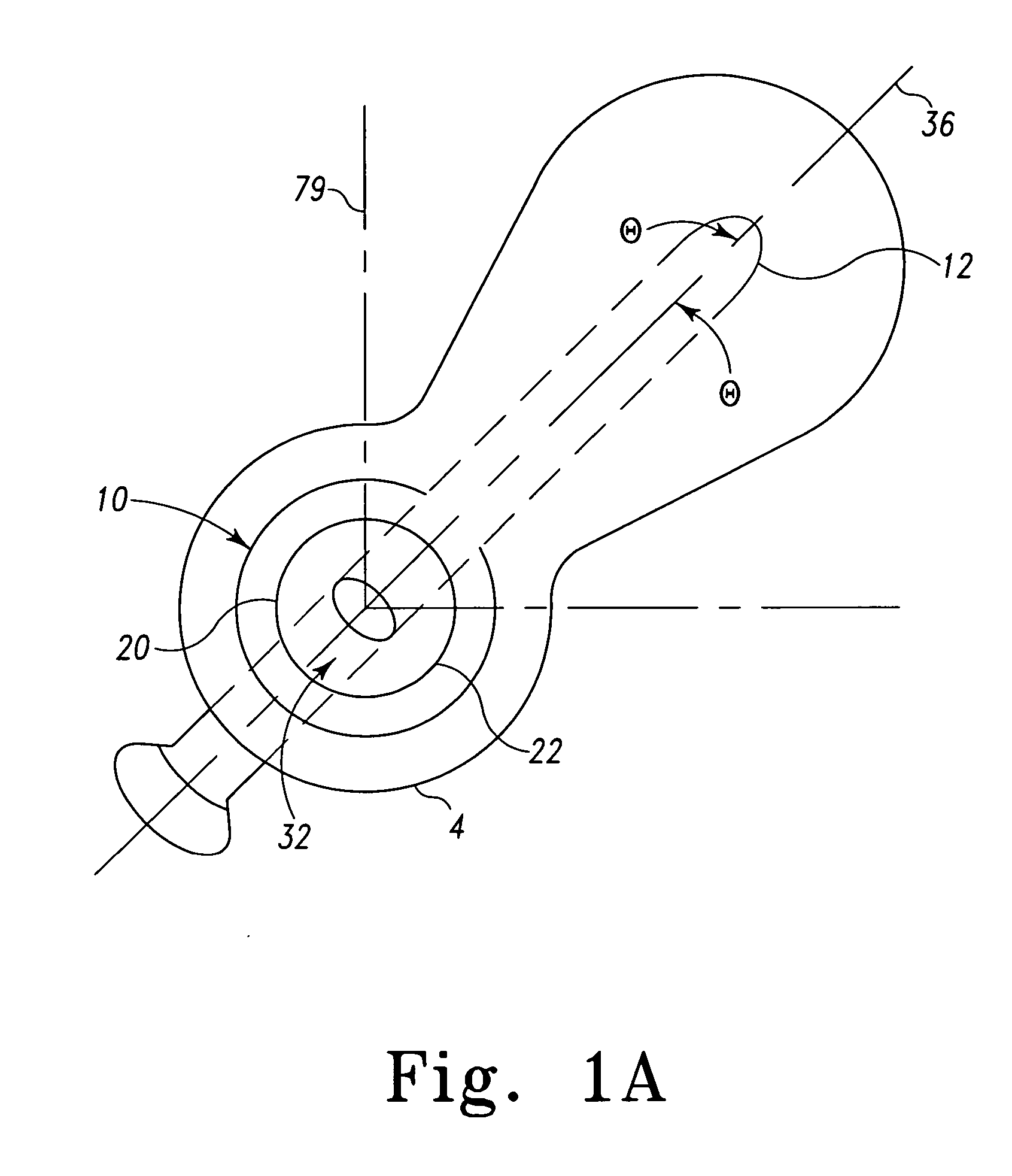
[0129] According to the present invention and referring now to FIG. 1, an intramedullary nail assembly 10 is shown for use with a screw 12 in an intramedullary canal 2 of a long bone 4. The nail assembly 10 includes a nail 14. The nail 14 is adapted for positioning at least partially in the medullary canal 2. The nail 14 defines an aperture 16 through the nail 14. The nail 14 defines a longitudinal axis 18 of the nail 14.

[0130] The nail assembly 10 further includes a bushing 20. The bushing 20 is p...


PUM


Abstract

A fixture for use with an intramedullary nail having nail body and a screw feature for receiving a screw orientable with respect to the nail body is provided. The fixture is adapted to orient the screw feature with respect to the nail. The fixture includes a first portion for cooperation with the nail body and a second portion for cooperation with the nail body. The fixture also includes a third portion for cooperation with the screw feature. The third portion is capable of being positioned in a plurality of positions with respect to the first portion. The fixture also includes a first nail body-positioning feature for positioning the nail body with respect to the first portion of the fixture. The fixture also includes a second nail body-positioning feature for positioning the nail body with respect to the second portion of the fixture. The fixture also includes a screw feature-positioning feature for positioning the screw feature with respect to the third portion of the fixture.

Description

TECHNICAL FIELD OF THE INVENTION [0001] The present invention relates generally to the field of orthopaedics, and more particularly, to a device for securing a prosthetic component to bone for use in with orthopaedic trauma or orthopaedic joint products. CROSS-REFERENCE TO RELATED APPLICATIONS [0002] Cross-reference is made to the following applications: DEP5517USNP titled, “INTRAMEDULLARY NAIL IMPLANT ASSEMBLY, KIT AND METHOD”, DEP5720USNP titled, “INTRAMEDULLARY NAIL, INTRAMEDULLARY NAIL ASSEMBLY AND METHOD”, DEP5721USNP titled, “FIXTURE, INTRAMEDULLARY NAIL KIT AND METHOD OF PRESETTING A NAIL ASSEMBLY”, DEP5654USNP titled, “VARIABLE ANGLE INTRAMEDULLARY NAIL, KIT AND METHOD”, and DEP5722USNP titled, “VARIABLE ANGLE INTRAMEDULLARY NAIL, ASSEMBLY AND METHOD”, filed concurrently herewith which are incorporated herein by reference. BACKGROUND OF THE INVENTION [0003] The skeletal system includes many long bones that extend from the human torso. These long bones include the femur, fibu...

Claims


Application Information

Patent Timeline
IPC IPC(8): A61F2/30
CPCA61B17/7241A61B17/748A61B17/744
Inventor METZINGER, ANTHONY J.
Owner DEPUY PROD INC
Why Eureka
Try Eureka