Tibia cutter

a technology of tibia and base plate, which is applied in the field of tibia cutter and base plate, can solve the problems of side effects and shorten the life of artificial knee joints

Inactive Publication Date: 2007-10-04
SEO JAI GON +1
View PDF24 Cites 36 Cited by
  • Summary
  • Abstract
  • Description
  • Claims
  • Application Information

AI Technical Summary

Benefits of technology

[0013] Therefore, it is an object of the present invention to provide a tibia cutter and a base plate for installing an artificial tibia insert at an exact position by indicating the information about the position of fitting the artificial tibia insert on the cut section of the tibia in knee arthroplasty.
[0014] In accordance with the present invention, there is provided a tibia cutter comprising a body including a bone cutting slot horizontally formed at the upper portion of the body to insert an electric saw for cutting the tibia top-end, a plurality of pinholes horizontally formed under the bone cutting slot of the body to insert fixing pins to be driven into the tibia, an alignment groove vertically formed at the rear side of the body to insert an alignment shaft of a tibia crus alignment device, and an indication hole formed forward and backward along the bone cutting slot in said bone cutting slot; and an indication pin which is inserted into said indication hole to indicate information about the fitting position of artificial tibia insert on the cut section of the tibia that is cut by electric saw.
[0015] In accordance with another aspect of the present inventi...

Problems solved by technology

As a result, the relative motion between the artificial tibia insert 12 and the artificial femur insert 11 is not smo...

Method used


Image

  • Tibia cutter
  • Tibia cutter
  • Tibia cutter

Examples


first embodiment

[0035] FIGS. 4 to 6 are drawings for describing the first embodiment of a tibia cutter according to the present invention. Specifically, FIG. 4 is a perspective view of a tibia cutter according to a first embodiment of the present invention, FIG. 5 is a drawing showing the forming of a drain as information about the position of fitting an artificial tibia insert on a top-end cut section of the tibia according to the first embodiment of the present invention, and FIG. 6 is a drawing showing how a base plate is installed at a desired position on the cut section of the tibia according to the first embodiment of the present invention.

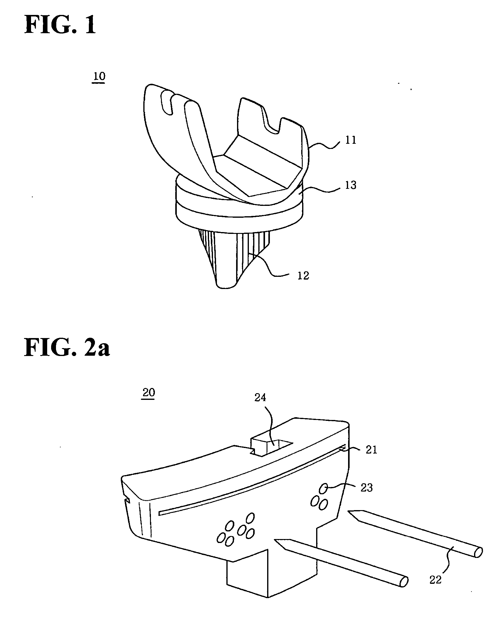
[0036] As shown in FIG. 4, the body of the tibia cutter 120 according to this embodiment comprises a bone cutting slot 121, a plurality of pinholes 123, an alignment groove 124 and an indication hole 125. The bone cutting slot 121 is horizontally formed at the upper portion of the body of the tibia cutter 20 to insert an electric saw for cutting the top-en...

second embodiment

[0043] As the second embodiment of the present invention, another preferred embodiment in which the indication hole of the tibia cutter is provided in another shape is shown in FIG. 7. Referring to FIG. 7, an indication hole 225 is formed forward and backward along a bone cutting hole 221 at a position perpendicular to an alignment groove 224, and furthermore the indication hole 225 has a semi-circular cross section shape and the indication pin 226 has a shape corresponding to that of the indication hole 225. The bottom side of the indication hole 225 is in contact with the bottom surface of the bone cutting slot 224.

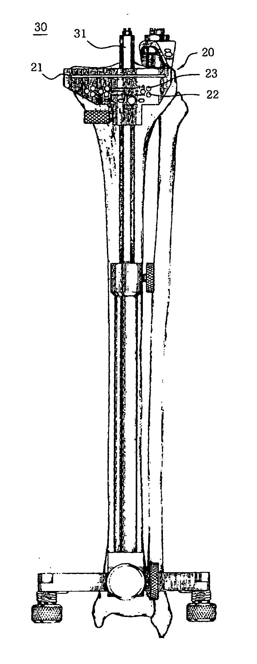
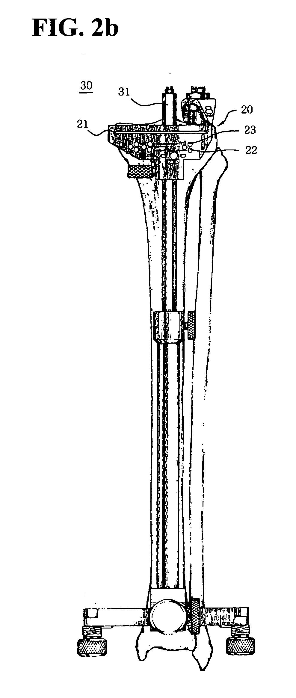
[0044] To use the tibia cutter configured like above, first, as shown in FIG. 2b, align the tibia crus in accordance with the mechanical axis using the tibia crus alignment device 30. Next, insert the alignment shaft 31 of the tibia crus alignment device 30 into the alignment groove 224 of the tibia cutter, and insert each of the fixing pins 222 into each of the alignm...

third embodiment

[0047] Since the tibia cutter according to the third embodiment is substantially similar to the tibia cutter according to the second embodiment, only the differences will be described.

[0048] As shown in FIG. 10, the tibia cutter according to this embodiment is characterized in that a marker hole 327 is formed in the lengthwise center of the indication pin 326. And, the shape of the indication hole 225 into which the indication pin 226 is inserted is identical with the one in the second embodiment. We will take a look at the surgery method: Like the second embodiment, insert an electric saw into the bone cutting slot 321 to cut the top-end of the tibia and insert the indication pin 326 into the indication hole 325. Next, put the indication pin 326 on the top-end cut section of the tibia, and pass a marker through the marker hole 327 formed on the indication pin 326 to draw a line. Accordingly, as shown in FIG. 8, a line, which is in accordance with the alignment line of the alignmen...


PUM


Abstract

A tibia cutter, which enables the artificial tibia insert to be installed at the exact position by indicating information about the fitting position of the artificial tibia insert on the cut section of the tibia, is disclosed. The tibia cutter comprises a body including a bone cutting slot horizontally formed at the upper portion of the body, a plurality of pinholes horizontally formed under the bone cutting slot of the body, an alignment groove vertically formed at the rear side of the body, and an indication hole formed forward and backward along the bone cutting slot in said bone cutting slot; and an indication pin which is inserted into said indication hole to indicate information about the fitting position of artificial tibia insert on the cut section of the tibia that is cut by electric saw.

Description

BACKGROUND OF THE INVENTION [0001] 1. Field of the Invention [0002] The present invention relates to a tibia cutter and a base plate, and more specifically to a tibia cutter and a base plate in which the artificial tibia insert can be installed at the exact position in artificial knee joint replacement surgery by indicating information about the installation position of the artificial tibia insert on the cut section of the tibia. [0003] 2. Description of the Related Art [0004] Knee arthroplasty, for replacing a knee joint damaged or deformed due to congenital deformation, traumatic injuries, diseases, or degenerative arthritis, etc. with an artificial knee joint, is widely performed. [0005] We will take a brief look at such knee arthroplasty: After cutting the bottom end of femur and the top-end of the tibia to replace the damaged knee joint with an artificial knee joint 10, an artificial femur insert 11 shown in FIG. 1 is fitted to the bottom end of the cut femur, and an artificial...

Claims


Application Information

Patent Timeline
IPC IPC(8): A61F5/00
CPCA61B17/1764A61B17/157
Inventor SEO, JAI-GONKIM, CHONG-BUM
Owner SEO JAI GON
Why Eureka
Try Eureka