Method for optimizing spatial orientations of computer-aided design models

a technology of computer-aided design and spatial orientation, applied in the field of rapid manufacturing of three-dimensional objects, can solve the problem that the spatial orientation of the cad model is not necessarily optimal for build performance, and achieve the effect of improving build performan

Active Publication Date: 2007-10-04
STRATSYS INC
View PDF68 Cites 84 Cited by
  • Summary
  • Abstract
  • Description
  • Claims
  • Application Information

AI Technical Summary

Benefits of technology

[0004] The present invention relates to a method, and system that performs the method, for building one or more 3D objects from a CAD model having an initial spatial orientation in a coordinate system. The method i

Problems solved by technology

However, the spatial orientation of the CAD model

Method used


Image

  • Method for optimizing spatial orientations of computer-aided design models
  • Method for optimizing spatial orientations of computer-aided design models
  • Method for optimizing spatial orientations of computer-aided design models

Examples


Embodiment Construction

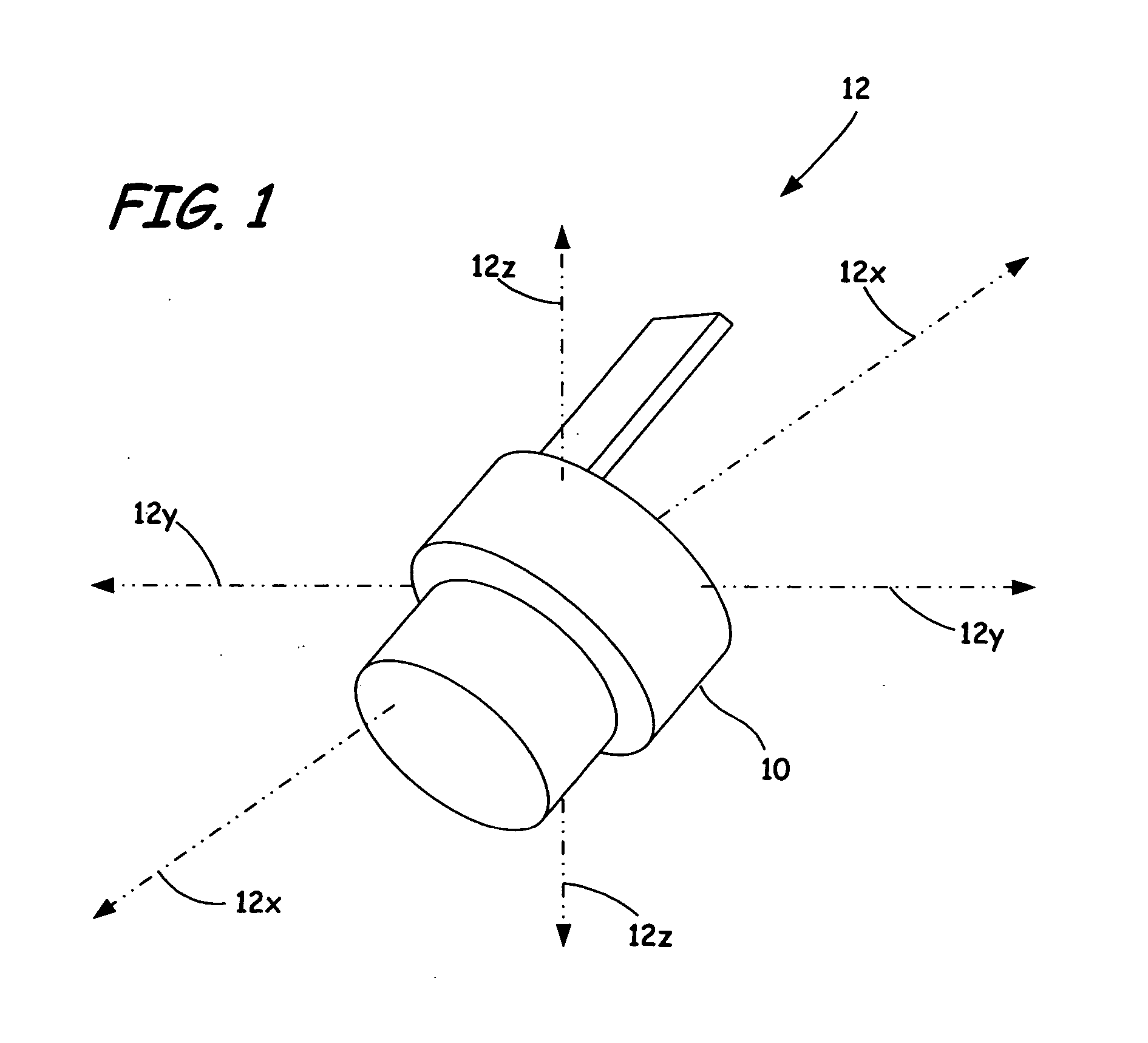
[0033]FIG. 1 is a perspective view of CAD model 10 located within coordinate system 12, where CAD model 10 is a geometric computer model of a 3D object (e.g., STL file). Coordinate system 12 is a Cartesian coordinate system that represents an area in which CAD model 10 is spatially oriented. In alternative embodiments, other coordinate systems may be used (e.g., cylindrical coordinate systems). Coordinate system 12 includes x-axis 12x, y-axis 12y, and z-axis 12z, where axes 12x and 12y define a horizontal x-y plane, and axis 12z defines a vertical axis orthogonal to the horizontal x-y plane. CAD model 10 is spatially oriented in coordinate system 12 such that axes 12x, 12y, and 12z generally intersect at a central location of CAD model 10.

[0034] Prior to optimizing the spatial orientation of CAD model 10 using the method of the present inverition, the spatial orientation of CAD model 10 in coordinate system 12 is referred to as an “initial spatial orientation”. Typically this refer...


PUM


Abstract

A method and system for building one or more three-dimensional objects, where the method includes providing a computer-aided design model of a three-dimensional object having an initial spatial orientation in a coordinate system, and determining an optimal spatial orientation of the computer-aided design model in the coordinate system based on one or more criteria.

Description

BACKGROUND OF THE INVENTION [0001] The present invention relates to the rapid manufacturing of three-dimensional (3D) objects such as prototypes, tooling, and production-quality parts, based on computer-aided design (CAD) models. In particular, the present invention relates to a method for optimizing spatial orientations of CAD models to improve build performance during rapid manufacturing. [0002] The production and testing of 3D objects is commonly used for developing new products, machines, and processes in a wide range of industries. There are a variety of rapid manufacturing techniques for building 3D objects, each of which develop 3D objects from CAD models under computer control. The term “rapid manufacturing” herein refers to the building of 3D objects by one or more layer-based additive techniques. Exemplary rapid manufacturing techniques include fused deposition modeling, ink jetting, selective laser sintering, electron-beam melting, and stereolithographic processes. [0003]...

Claims


Application Information

Patent Timeline
IPC IPC(8): G06F19/00G06T19/20
CPCG06F17/50B33Y50/00G06F2113/10G06F30/20B33Y50/02G06F30/00
Inventor HEIDE, ERIK K.HOLZWARTH, DONALD J.
Owner STRATSYS INC
Why Eureka
Try Eureka