Door stop pin assembly

a technology for preventing pins and doors, which is applied in the field of door stops, can solve problems such as problems such as problems such as and achieve the effect of avoiding the problem of alignment and the relative motion between the door and the door fram

Active Publication Date: 2007-10-11
KAMATICS
View PDF13 Cites 10 Cited by
  • Summary
  • Abstract
  • Description
  • Claims
  • Application Information

AI Technical Summary

Problems solved by technology

Door stop pin assemblies may be found in applications such as aircraft passenger doors, cargo doors, and emergency exit doors, where alignment and the relative motion between the door and doorframe can be problematic.
The conventional configuration results ...

Method used


Image

  • Door stop pin assembly
  • Door stop pin assembly

Examples


Embodiment Construction

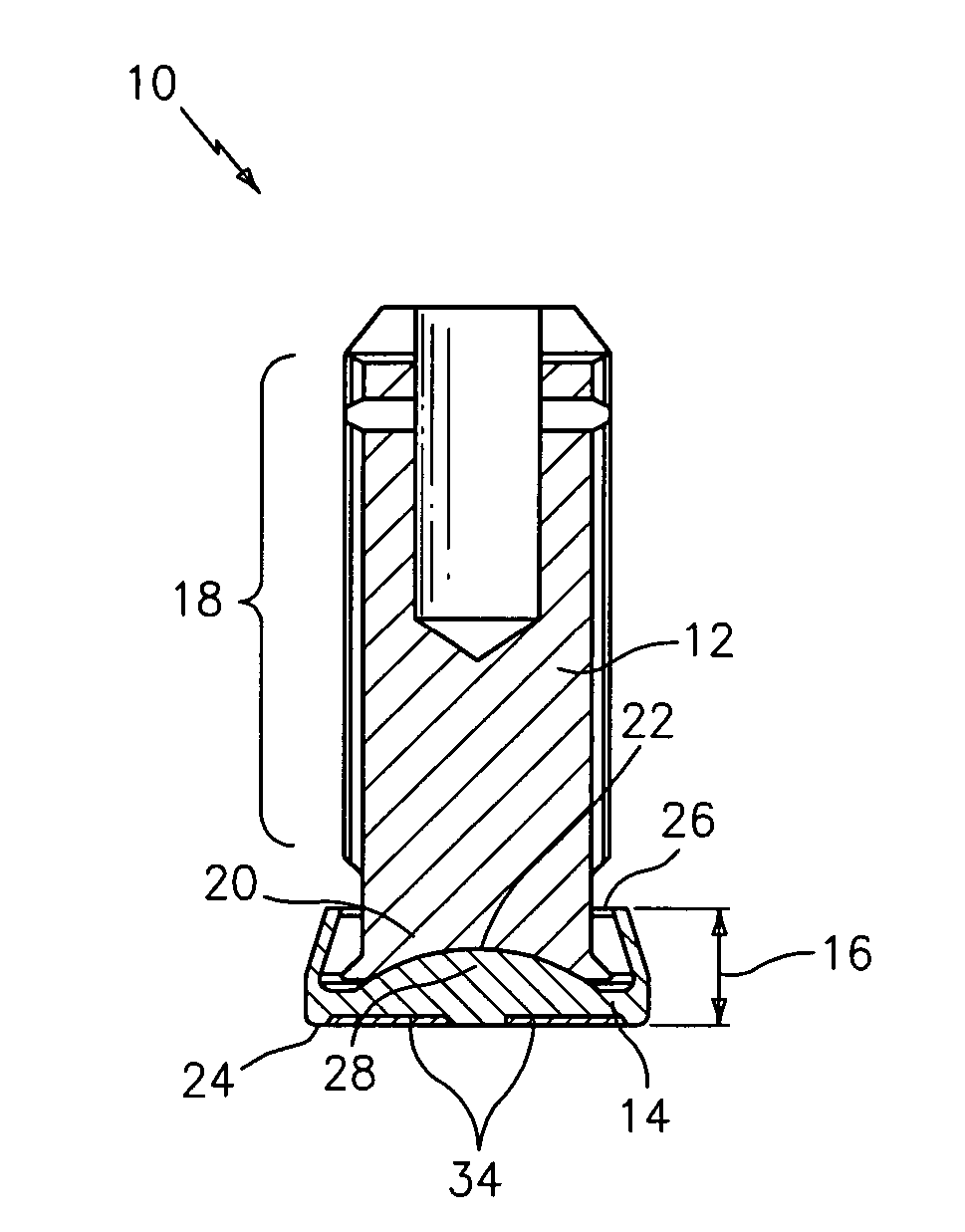
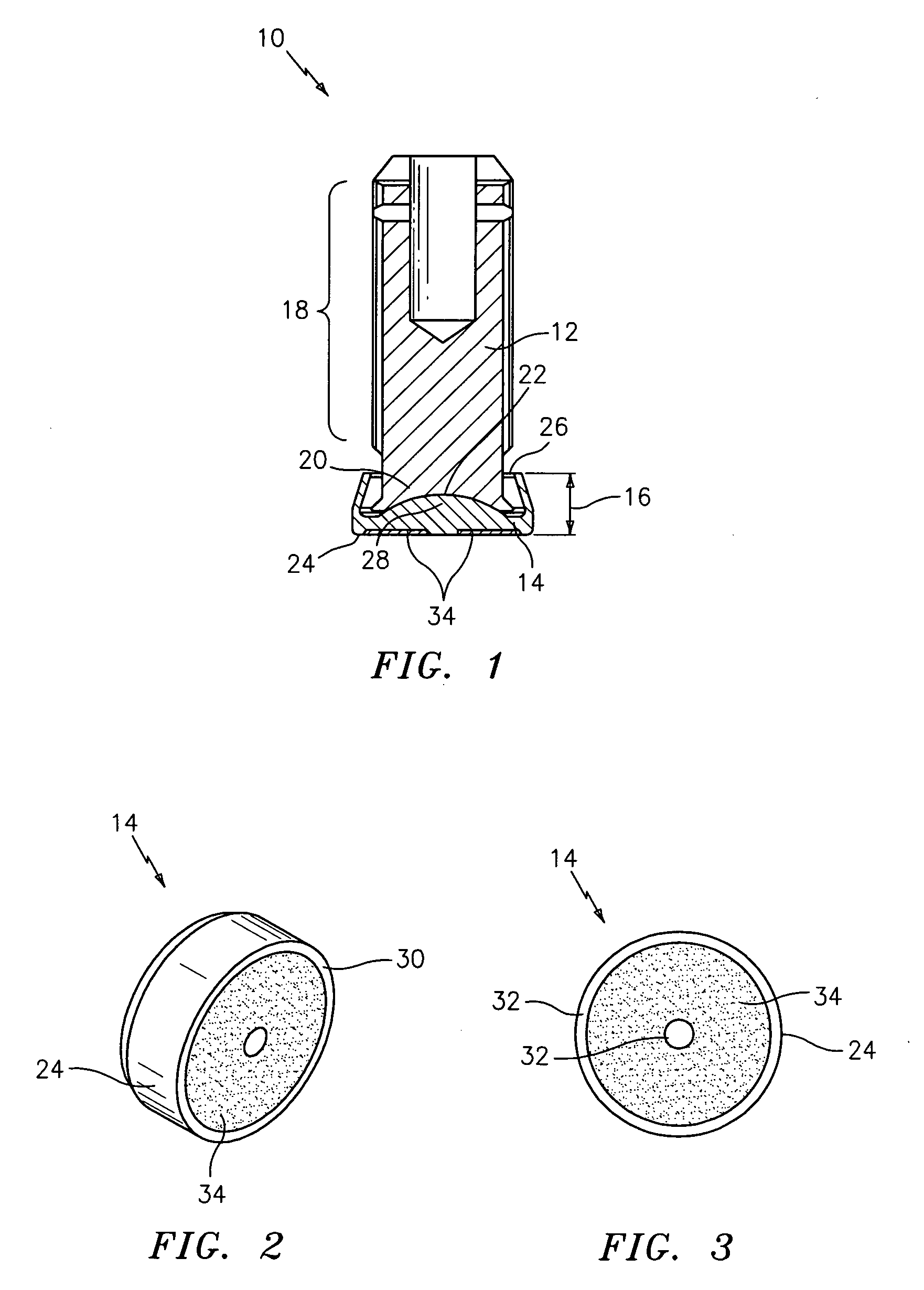
[0011] Referring to FIG. 1, an exemplary embodiment of a door stop pin assembly 10 that, for example, in one embodiment can be used in aircraft door applications, is illustrated. The door stop pin assembly 10 comprises a pin 12 and a mating base pad 14. The base pad 14 is able to misalign in all directions relative to the pin 12 while providing a positive stop between a door assembly (not shown) and a doorframe support structure (not shown). The misalignment capability of the base pad 14 reduces the onset of galling and also minimizes contact stresses between the door stop pin assembly 10 and the doorframe support structure. The disclosed pin 12 and base pad 14 configuration provides many significant advantages over conventional configurations including a reduced base pad height 16, which allows the use of the door stop pin assembly 10 in smaller design envelopes, and a conductive path between the pin 12 and the base pad 14, which eliminates the need for separate wires to be connect...


PUM


Abstract

Disclosed herein is a door stop pin assembly including a pin and a base pad. The pin has a concave spherical recess. And, the base pad has an open end and a closed end such that the open end has a convex spherical portion in contact with the concave spherical recess.

Description

TECHNICAL FIELD [0001] This application relates generally to a door stop, and more specifically, to an aircraft door stop pin assembly which provides a positive stop between a door and a surrounding structure, while allowing for misalignment between the two. BACKGROUND OF THE INVENTION [0002] Door stop pin assemblies are generally used in aircraft to ensure that contact and transmission of loads between a door assembly and a doorframe support structure is absorbed by lubricated hard points, negating any fretting or galling, which might occur due to relative motion. Relative motion between the two structures may occur due to cyclic pressurization of the fuselage and / or flight loads imposed on the external surfaces of the aircraft. Door stop pin assemblies may be found in applications such as aircraft passenger doors, cargo doors, and emergency exit doors, where alignment and the relative motion between the door and doorframe can be problematic. [0003] Conventional door stop pin assem...

Claims


Application Information

Patent Timeline
IPC IPC(8): E05F5/02
CPCB64C1/14Y10T16/61E05Y2900/502E05F7/04
Inventor RUTLEDGE, THOMAS P.ATKINSON, ROBERT
Owner KAMATICS
Why Eureka
Try Eureka