Axial locking device for turbine blades

a technology of turbine blades and locking devices, which is applied in the direction of liquid fuel engines, vessel construction, marine propulsion, etc., can solve the problems of high assembly effort, high manufacturing and assembly costs, and less axial displacement of blade root relative to turbine disks, etc., and achieves increased surge losses or leakages, low weight, and low cost. , the effect of increasing the surge loss or leakag

Inactive Publication Date: 2007-12-18
ROLLS ROYCE DEUT LTD & CO KG
View PDF7 Cites 10 Cited by
  • Summary
  • Abstract
  • Description
  • Claims
  • Application Information

AI Technical Summary

Benefits of technology

[0006]A broad aspect of the present invention is to provide a turbine blade locking device of the type specified above which, while being characterized by simple design, easy and cost-effective manufacture and easy assembly, provides for a high degree of reliability and safety.
[0009]It is, therefore, not required to secure the turbine blades on the disk rim or the turbine disk by means of locking plates or cover plates or locking rings. Rather, it is sufficient to insert a ball which is inexpensively procurable and, moreover, is characterized by low weight and does not require further assembly aids or auxiliary components.
[0011]Accordingly, a light and cost-effective design is provided which is characterized by simple assembly and easy and unproblematic disassembly. Favorable force conditions result in lower mechanical loading, leading to an increase in the overall life of the turbine.
[0012]It is particularly favorable to provide the retaining groove with a partly spherical axial end area, enabling the associated surface of the ball to be precisely positioned and held for the transfer of forces. Obviously, the center axis of the recess accommodating one ball half preferably agrees, or coincides, with the radial center axis of the semi-spherical end area of the groove, providing for a precision of fit between the turbine blade and the turbine disk.

Problems solved by technology

Disadvantages here are the high assembly effort and the risk that these fixations may work loose or be inaccurately fitted, resulting in at least a slight axial displacement of the blade root relative to the turbine disk.
A further disadvantage is the higher mass of the total design and the considerable manufacturing and assembly costs.
Another disadvantage lies in the fact that serviceability and reliability are not always ensured or that relatively expensive inspection activities are required to check for correctness of assembly.

Method used


Image

  • Axial locking device for turbine blades
  • Axial locking device for turbine blades
  • Axial locking device for turbine blades

Examples


Embodiment Construction

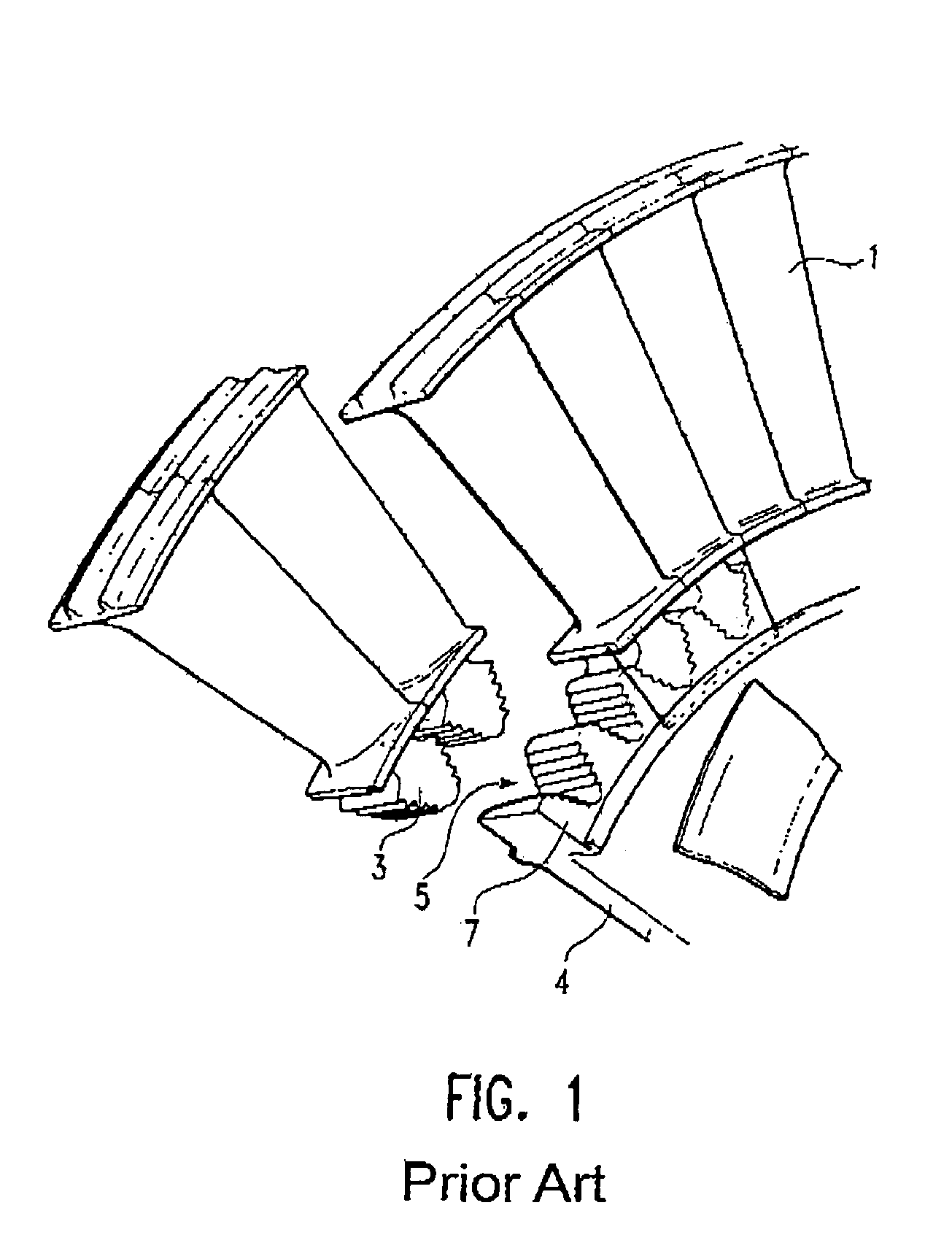
[0018]FIG. 1 shows in schematic representation part of a turbine disk 4 with several disk lobes 7 forming axial lobe slots 5 into which blade roots 3 of turbine blades 1 are axially insertable. The contour of the lobe slot 5 and the blade roots 3 is selected such that a precision of fit is guaranteed. FIG. 1 shows that locking plates, or similar, are used for axial retention in the state of the art.

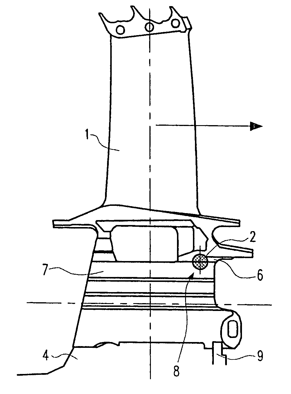
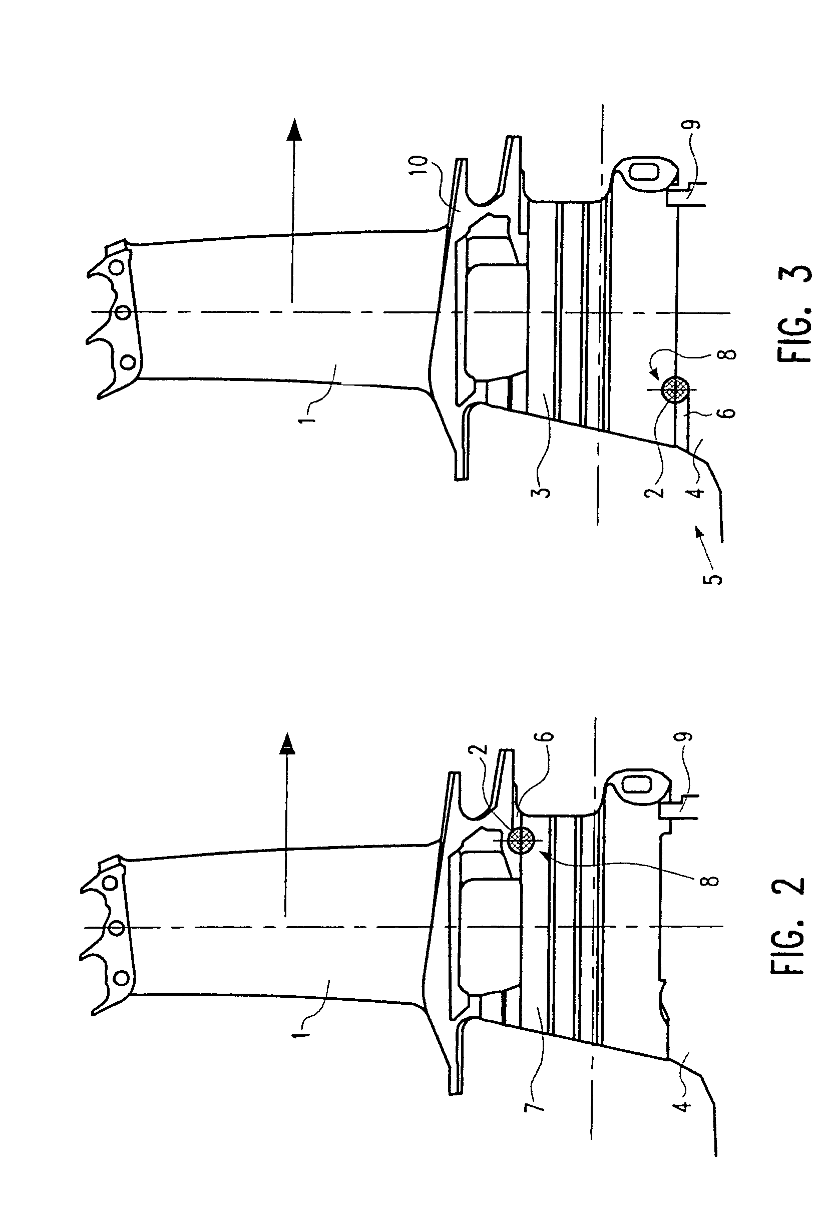
[0019]FIG. 2 shows, in a side view, a turbine blade 1 and a partial area of the turbine disk 4. FIG. 2 is a side view in which a ball 2 is arranged half in a semi-spherical seat (recess 8) machined in the disk lobe 7. A retaining groove 6 with semi-spherical cross-section is machined into the rearward sealing fin of the blade platform enabling the blade 1 to be installed from forward into the disk rim (turbine disk 4). Accordingly, the ball 2 is fitted first, then the turbine blade 1 inserted in the direction of the arrowhead. For additional retention, a retaining element 9, which can be ...


PUM


Abstract

A turbine blade locking device for axial retention of a turbine blade (1) having a blade root (3) inserted in an axially extending profiled lobe slot (5) of a turbine disk (4), wherein, a sealing fin of a blade platform (10) includes, over part of its axial length, a retaining groove (6) featuring a semicircular cross-section, a disk lobe (7) of the turbine disk (4) is provided with a semi-spherical recess (8), and a ball (2) is fitted into the recess (8) and the retaining groove (6).

Description

[0001]This application claims priority to German Patent Application DE 10 2005 024 932.9 filed May 31, 2005, the entirety of which is incorporated by reference herein.BACKGROUND OF THE INVENTION[0002]This invention relates to a turbine blade locking device for axial retention of a turbine blade on the turbine disk.[0003]In the state of the art it is known to provide the blade roots of turbine blades with a profile to take up the radially directed forces occurring during the operation of a gas turbine. In order to prevent the blade root from moving axially relative to the turbine disk, a means of retention is required. Such means of retention are shown in Specifications EP 0 610 668 B1, U.S. Pat. No. 5,135,354 or U.S. Pat. No. 5,518,369 by way of example.[0004]In the designs known from the state of the art, plate-type elements (locking plates, cover plates and locking rings) are usually fitted which, together with abutments on the blade roots or the turbine disks, provide for axial r...

Claims


Application Information

Patent Timeline
Patent Type & Authority Patents(United States)
IPC IPC(8): F01D5/32
CPCF01D5/326F05D2250/241
Inventor NEGULESCU, JOANA
Owner ROLLS ROYCE DEUT LTD & CO KG
Why Eureka
Try Eureka