
Adaptive solar powered system

a solar power system and solar energy technology, applied in the field of solar power systems, can solve the problems of increasing the amount of power available to the system, increasing the design difficulty of the system, and increasing the energy requirements of the lighting system

Inactive Publication Date: 2007-10-11
CARMANAH TECHNOLOGIES INC
View PDF20 Cites 179 Cited by
  • Summary
  • Abstract
  • Description
  • Claims
  • Application Information

AI Technical Summary

Benefits of technology

[0011] In yet another aspect, the invention comprises a method of determining a time to deliver an amount of energy to a load in a solar powered system comprising monitoring an output of a solar panel to determine a start of day, monitoring the output of the solar panel to determine...

Problems solved by technology

For instance, the latitude and weather conditions in a given installation location significantly affect the amount of power available to the system.
When the operating times are determined by the user, design of the system becomes more difficult because the amount of energy used by the system over a given time period may be unknown at the time of design or installation of the system.
Thus, the lighting system requires more energy.
Since solar powered lighting is often installed in areas where access to communications infrastructure is limited, maintaining the time of day using conventional means such as through wired or wireless communications may be difficult.

Method used


Image

  • Adaptive solar powered system
  • Adaptive solar powered system
  • Adaptive solar powered system

Examples


Embodiment Construction

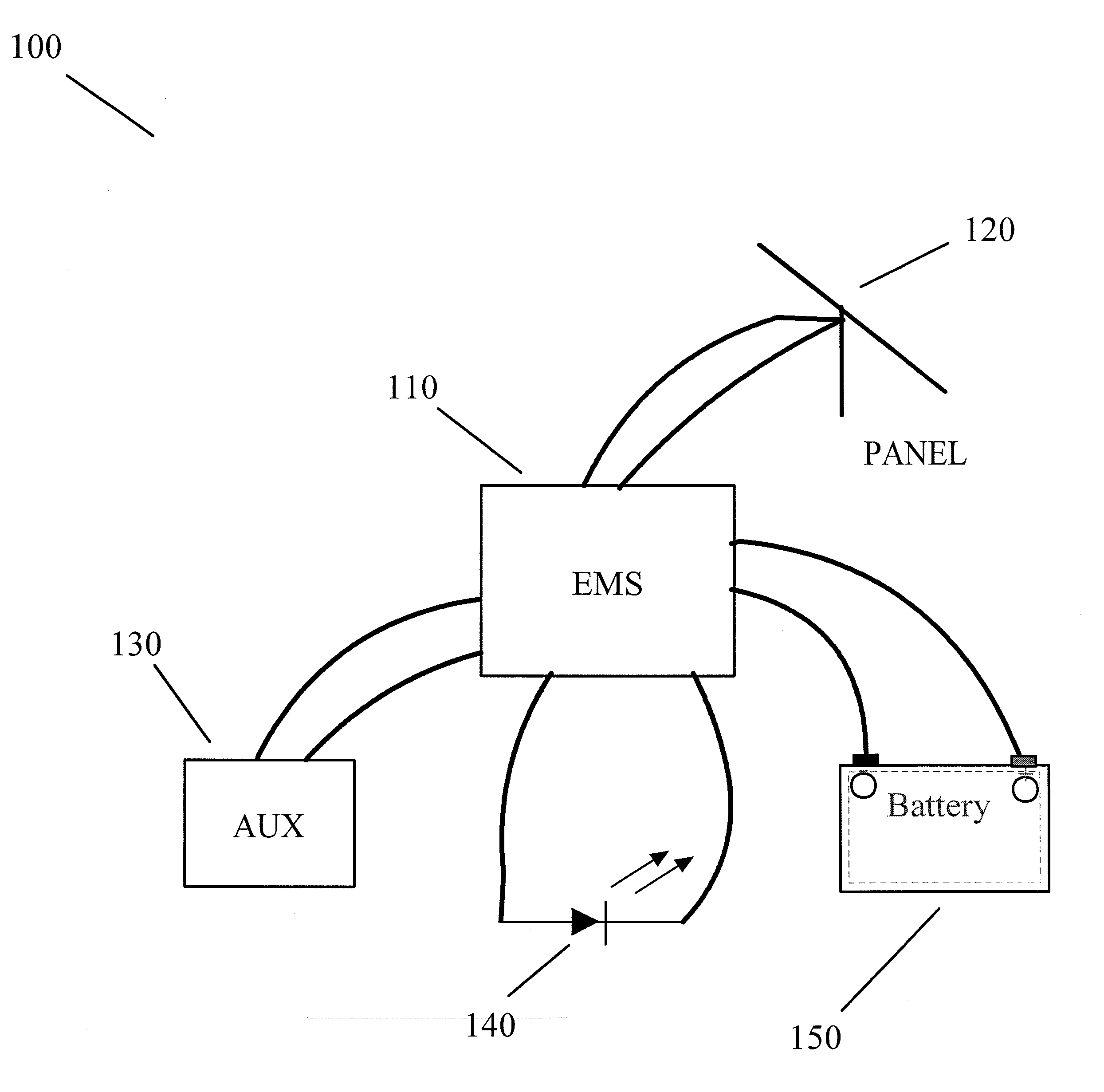
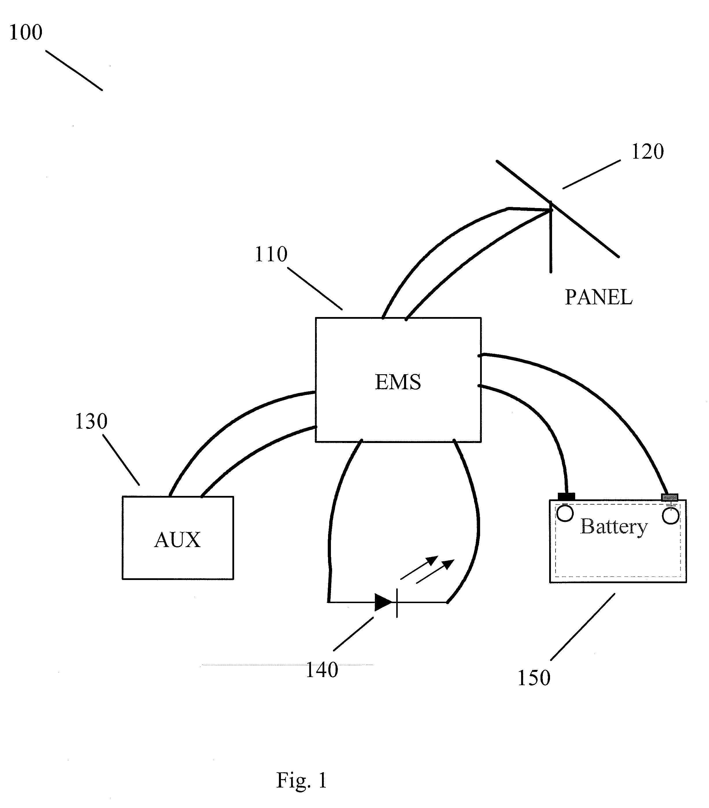
[0020]FIG. 1 is a diagram of solar powered system 100. The solar powered system comprises an energy management system (EMS) 110. The EMS 110 is coupled to a solar panel 120 for receipt of energy from the sun. The EMS 110 is coupled to a battery 150 for storage of energy. Alternatively, another energy storage device such as a supercapacitor, fuel cell, etc. may be used. The EMS 110 is coupled to a load 140 (such as an LED or LEDs) to which the EMS may provide power. Auxiliary circuitry 130 may use power from the EMS 110 or provide or receive other signals from the energy management system 110. Auxiliary circuitry may comprise for example a pedestrian pushbutton, motion detector, etc.

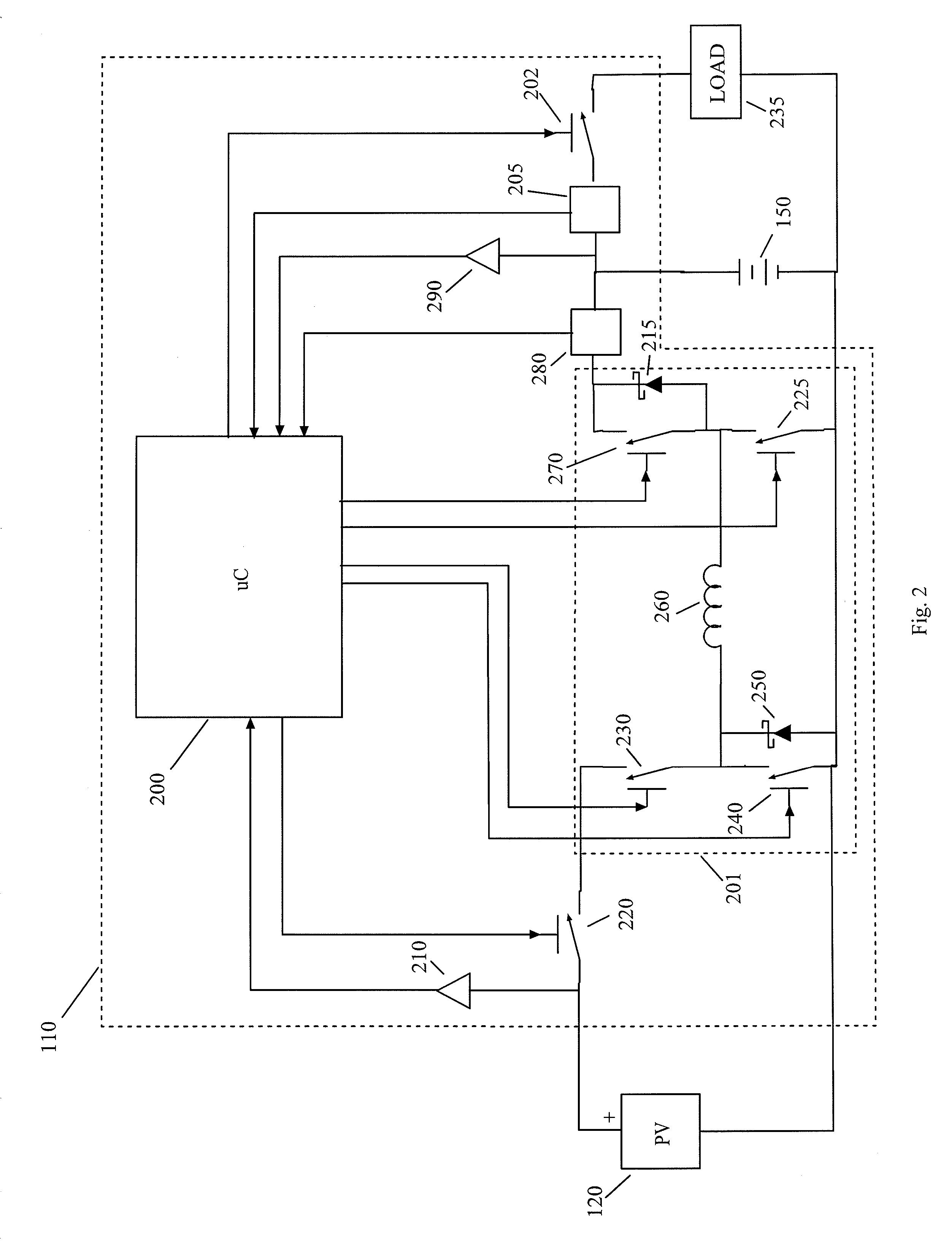
[0021]FIG. 2 is a schematic diagram of an example implementation of the EMS 110. In this figure, standard support circuitry known to be necessary in the field has been omitted for clarity. A processor 200 controls the operation of the EMS 110. The processor may comprise a microcontroller, microprocessor ...


PUM


Abstract

An apparatus for powering a load from solar energy comprises a DC / DC converter, battery terminals coupled to an output of the DC / DC converter and coupleable to an energy storage device, and solar panel terminals coupled to an input of the DC / DC converter and coupleable to a solar panel. Logic is coupled to the converter to control its conversion rate. A detector is coupled to the converter and detects its power output. The logic is operable to adjust the conversion rate until the solar panel operates at the smaller of a maximum power point of the solar panel and a power point of the solar panel that results in a maximum desired power.

Description

FIELD OF THE INVENTION [0001] This invention relates to solar power systems and in particular to power management subsystems for solar power systems. BACKGROUND OF THE INVENTION [0002] Solar powered systems provide benefits such as reduced installation cost, the ability to be installed in areas where no other source of energy is available, etc. Typically, a solar powered system will consist of a solar panel, battery, load (such as a light emitting diode) and associated circuitry. The associated circuitry controls charging of the battery, load operating times and load operating levels. [0003] Sizing of the solar panel or panels, battery or batteries for a given installation requires many inputs for optimal cost for a given performance requirement. For instance, the latitude and weather conditions in a given installation location significantly affect the amount of power available to the system. In addition, if the location of installation can be shaded by buildings, trees, etc., it ma...

Claims


Application Information

Patent Timeline
IPC IPC(8): H02N6/00
CPCH02J7/35Y02B70/1466H02M3/1588Y02B70/10
Inventor WORK, JASON N.WYPER, NEIL D.LIGHTBODY, SIMON H.
Owner CARMANAH TECHNOLOGIES INC
Learn More