Apparatus for Materials Reduction

Inactive Publication Date: 2007-10-11
JOHNSON RAYMOND WILLIAM
View PDF0 Cites 18 Cited by
  • Summary
  • Abstract
  • Description
  • Claims
  • Application Information

AI Technical Summary

Problems solved by technology

The costs for disposing the above materials are accordingly high.
The prior art shredding machines therefore do not meet the requirements of such organisations including the mi

Method used


Image

  • Apparatus for Materials Reduction
  • Apparatus for Materials Reduction
  • Apparatus for Materials Reduction

Examples


Embodiment Construction

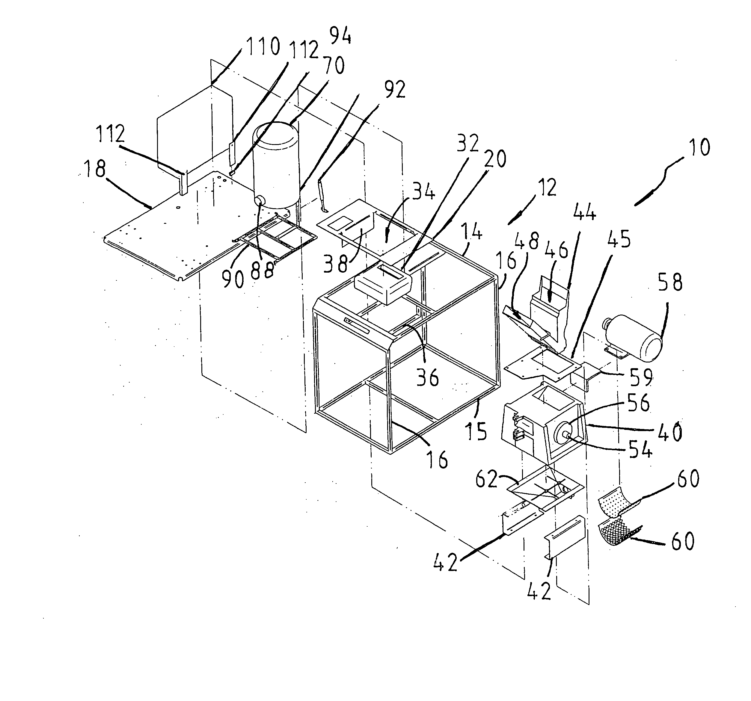
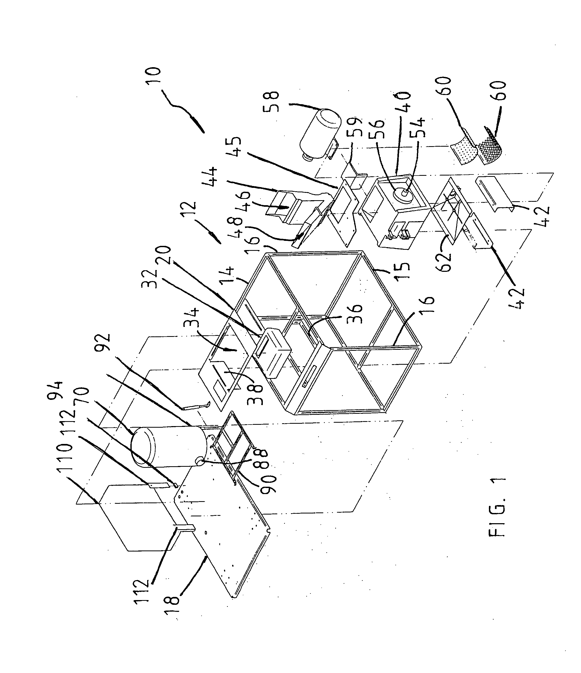
[0037] Referring initially to FIG. 1 there is shown an embodiment of the apparatus 10 according to the present invention. The apparatus 10 as shown has a frame 12 formed of a top and bottom sets of connected horizontal elongate members 14 and 15, and vertical elongate members 16 interconnecting said top and bottom sets. A support panel 18 is fixed to the bottom horizontal elongate members 15 of the frame 12, and a cover panel 20 is fixed to the top horizontal elongate members 14.

[0038] As shown more clearly in FIG. 6, the apparatus 10 has a materials reduction station 22, a holding station 24 and a disposal station 26. The reduction station 22 includes a first reduction zone 28 and a second reduction zone 30. First cutting means 32 in the form of a cross-cut shredder is positioned in a recess 34 of the cover panel 20. A U-shaped support element 36 fixed to two adjacent elongate members 14 and down turned flanges 38 of the cover panel 20 are arranged to maintain the shredder 32 in p...


PUM


Abstract

Apparatus for reducing materials for disposal having a frame for supporting a material reduction station, a holding station and a disposal station. The reduction station has a first and second reduction zone and a hopper with a first passage arranged to convey materials reduced or shredded by cutting elements to second cutting elements, and a second passage arranged to convey materials directly to the second cutting elements. The second passage has a retardation arrangement for retarding materials downstream from flowing past and out through the second passage. A perforated screen cooperates with the second cutting elements to reduce the materials to a size determined by the size of the perforations. The holding station includes a tray having a holding space for temporarily holding reduced materials from the second reduction zone, and an outlet port in communication with a container in the disposal station.

Description

TECHNICAL FIELD OF THE INVENTION [0001] THIS INVENTION relates generally to an apparatus for material reduction, and in particular but not limited thereto, the apparatus having material reduction means for reducing materials into a predetermined particle size, suction means for guiding the reduced materials into a container for disposal. BACKGROUND OF THE INVENTION [0002] People working in business and government organisations use paper materials for taking notes, writing, or drafting and printing reports and correspondence. The usage of paper materials in these organisations continue to grow significantly despite the advent of the personal computers intended to facilitate “paperless” offices. People in these organisations also generally use a large volume of other materials such as packaging containers, paper and plastic containers for food items, and plastic bottles and metal cans for beverages. Following consumption, the above materials are normally stored in bins to be emptied r...

Claims


Application Information

Patent Timeline
IPC IPC(8): B02C18/04B02C18/00B02C18/14B02C18/16B02C18/22B02C23/16B65F1/00
CPCB02C18/0007B02C18/0084B02C18/16B02C18/2216B02C18/2291B65F1/0033B02C2018/0046B02C2018/147B02C2018/168B02C2023/165B02C2018/0023Y02W30/10
Inventor JOHNSON, RAYMOND WILLIAM
Owner JOHNSON RAYMOND WILLIAM
Why Eureka
Try Eureka