
Lithographic apparatus and device manufacturing method utilizing a MEMS mirror with large deflection using a non-linear spring arrangement

a technology of mems mirror and non-linear spring arrangement, which is applied in the direction of photomechanical apparatus, instruments, optics, etc., can solve the problems of non-linear relationship between the voltage applied to the electrostatic actuator and the displacement of the mirror, and the control system is necessarily complex and requires a significant amount of memory

Inactive Publication Date: 2007-10-11
ASML NETHERLANDS BV
View PDF31 Cites 13 Cited by
  • Summary
  • Abstract
  • Description
  • Claims
  • Application Information

AI Technical Summary

Benefits of technology

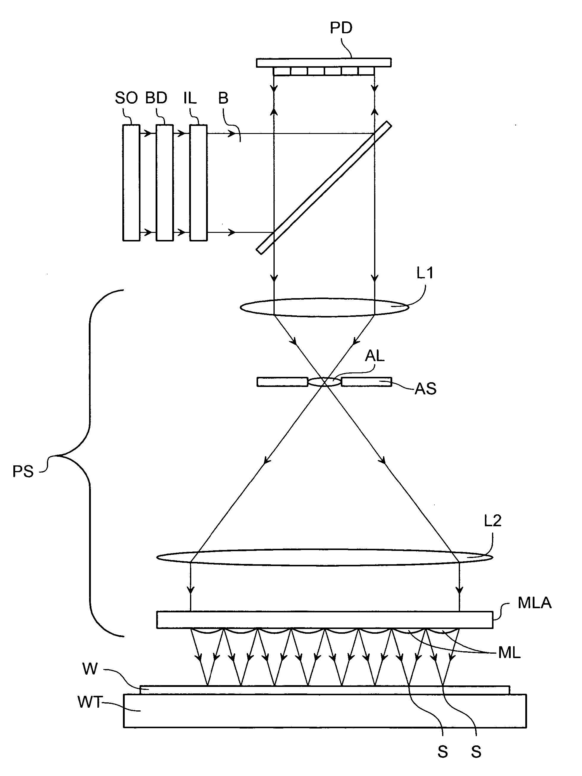
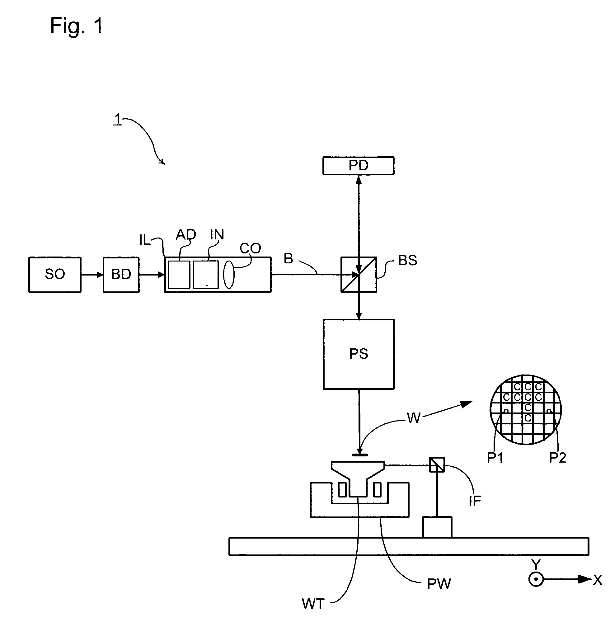
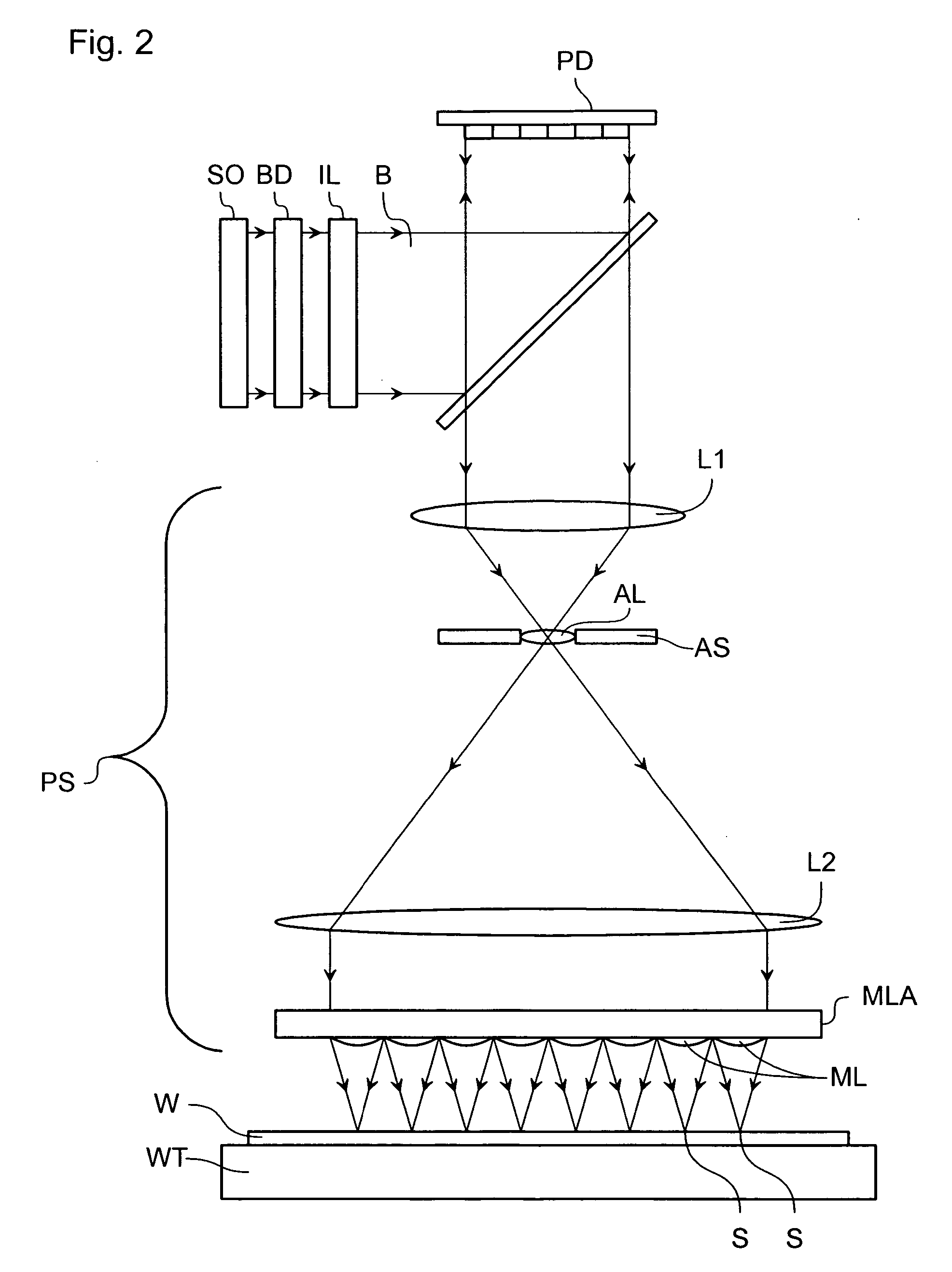
The present invention provides an array of individually controllable elements that can modulate a beam of radiation. The elements include a reflector and an actuator that can exert a force on the reflector to move it away from a first position to a second position. The force exerted on the reflector is non-linearly related to its displacement. The invention also provides a lithographic apparatus and a device manufacturing method that use the array of individually controllable elements to modulate the beam of radiation before it is projected onto a substrate. The technical effects of the invention include improved accuracy and precision in the modulation of the beam of radiation, as well as improved manufacturing efficiency and accuracy.

Problems solved by technology

Furthermore, the relationship between the voltage applied to the electrostatic actuator and the displacement of the mirror is non-linear.
Accordingly, the control system is necessarily complex because for each mirror, a required corresponding intensity of radiation at the substrate will need to be converted to a required voltage, necessary to generate a given displacement of the mirror that directs a given intensity of radiation into the projection system.
As a result of the non-linear relationship between the voltage and the displacement of the mirror, this determination is computationally complex or may be performed by lookup tables, thus requiring a significant amount of memory.
Furthermore, the configuration can be unstable and, above a given voltage applied to the actuator or a given displacement of the mirror, the mirror will snap through.

Method used


Image

  • Lithographic apparatus and device manufacturing method utilizing a MEMS mirror with large deflection using a non-linear spring arrangement
  • Lithographic apparatus and device manufacturing method utilizing a MEMS mirror with large deflection using a non-linear spring arrangement
  • Lithographic apparatus and device manufacturing method utilizing a MEMS mirror with large deflection using a non-linear spring arrangement

Examples


embodiment 1

[0091]FIGS. 7a, 7b, and 7c depict a configuration of an individually controllable element, according to a first embodiment of the present invention. For clarity, the actuator system is not shown. However, it will be appreciated that it can be the same as that depicted in FIG. 5. The individually controllable element 30 is comprised of a reflector 31 mounted by hinges 32 on supports 33, for example in the same manner as discussed above in relation to FIG. 5. Accordingly, as the reflector 31 rotates about an axis through the hinges 32, the hinges deform elastically exerting a force on the reflector 31 to bias the reflector towards its original position. The force exerted by the hinges 32 is proportional to the displacement from its original position. The individually controllable element 30 further includes an interceptor arrangement 34,35 that operates in the manner discussed below.

[0092] The interceptor arrangement includes an additional support 35 that is fixed relative to the rem...

embodiment 2

[0097]FIG. 9a depicts an arrangement of an individually controllable element, according to the second embodiment of the present invention. The second embodiment is a variation of the first embodiment, and only the differences thereof will be discussed. It should be appreciated that any variations discussed above in relation to the first embodiment can also be applicable to the second embodiment.

[0098] As depicted, the individually controllable element 40 includes a reflector 41 mounted by hinges 42 to first supports 43. The individually controllable element further includes a first set of resilient members 44 that interact with a first set of additional supports 45 after the reflector 41 has rotated by a first amount. Accordingly, the stiffness of the configuration is initially provided by the deformation of the hinges 42, and thereafter by the combination of the deformation of the hinges 42 and the deformation of the first set of resilient members 44. The individually controllable...

embodiment 3

[0100]FIG. 10 depicts an individually controllable element 50, according to a third embodiment of the present invention. The third embodiment is a variation of the first embodiment of the present invention and only the differences thereof will be described. It should be appreciated that variations of the first embodiment can also be applicable to third embodiment.

[0101] As depicted the individually controllable element 50 includes a reflector 51 rotatable about hinges 52 mounted to supports 53. As with the first embodiment, the individually controllable element of the third embodiment is configured such that after a given rotation of the reflector 51 an interceptor arrangement is configured such that an additional force is exerted on the reflector 51 by a resilient member such that the effective stiffness of the reflector arrangement increases for any further deflection. Whereas in the first embodiment, the resilient member is provided to the reflector and interacts with a support ...


PUM

PropertyMeasurementUnit
diameteraaaaaaaaaa
diameteraaaaaaaaaa
diameteraaaaaaaaaa

Abstract

An array of individually controllable elements for a lithographic apparatus comprise reflectors that can be actuated by an actuator and are biased to return to a given position by a force that varies non-linearly with the displacement of the reflector from that position.

Description

BACKGROUND [0001] 1. Field of the Invention [0002] The present invention relates to a lithographic apparatus, an array of individually controllable elements and a method for manufacturing a device. [0003] 2. Related Art [0004] A lithographic apparatus is a machine that applies a desired pattern onto a substrate or part of a substrate. A lithographic apparatus can be used, for example, in the manufacture of flat panel displays, integrated circuits (ICs) and other devices involving fine structures. In a conventional apparatus, a patterning device, which can be referred to as a mask or a reticle, can be used to generate a circuit pattern corresponding to an individual layer of a flat panel display (or other device). This pattern can be transferred onto all or part of the substrate (e.g., a glass plate), by imaging onto a layer of radiation-sensitive material (e.g., resist) provided on the substrate. [0005] Instead of a circuit pattern, the patterning device can be used to generate othe...

Claims


Application Information

Patent Timeline
Patent Type & Authority Applications(United States)
IPC IPC(8): G03B27/54
CPCG03F7/70291G02B26/0841
Inventor VENEMA, WILLEM JURRIANUS
Owner ASML NETHERLANDS BV
Learn More