System and method for fusion power generation using very high electrical potential difference

a technology of electrical potential difference and fusion power, which is applied in the field of system and method of fusion power generation using very high electrical potential difference, can solve the problems of not explaining the occasional high power generated, not explaining the great difference in peak current generated, and natural lightning not producing very high kilowatts of power, etc., and achieves sufficient net energy gain

Inactive Publication Date: 2007-10-11
CHEANG SIO HANG
View PDF0 Cites 8 Cited by
  • Summary
  • Abstract
  • Description
  • Claims
  • Application Information

AI Technical Summary

Benefits of technology

[0049] Whether a fusion reaction producing sufficient net energy gain to be attractiv

Problems solved by technology

On the contrary, some natural lightning do not produce very high kilowatts of power.
In fact, the theory of height between land and cloud does not explain t

Method used


Image

  • System and method for fusion power generation using very high electrical potential difference
  • System and method for fusion power generation using very high electrical potential difference
  • System and method for fusion power generation using very high electrical potential difference

Examples


embodiment 1

f Machine with Magnet System in Closed Spherical Space

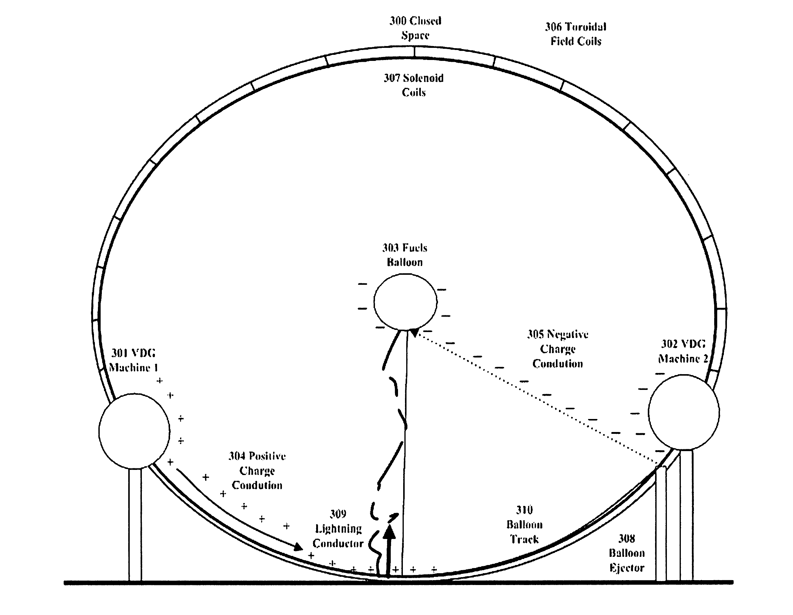
[0078] A typical cloud to ground lightning is created within the dome. Some fusionable materials, deuterium and tritium—two isotopes of hydrogen, are used to form a gas mixture. The gas mixture is injected into and contained in a balloon 303, which is produced and released from a balloon ejector 308 on a scheduled basis. The balloon will be fasted to a string and a thin wire. The thin wire will remain on top of the balloon ejector, near the VDG machine 302. The one end of the string will be fasted to the balloon, while the other end will be anchored on a metal ball. The metal ball will be slid down to the bottom of the balloon track 310.

[0079] As shown in FIG. 5, the balloon stuffing machine 508 will stuff the fusionable gas mixture 509 into a balloon mounted by robot arm 2 505, which also attaches a wire (from balloon wire 506) on the balloon while robot arm 2 501 will tighten a string (from balloon string 507) to the balloon w...

embodiment 2

f Machine without Magnet System in Very Large Closed Spherical Space

[0093] In the nature, where a thunderstorm grows over a tall Earth grounded object, such as a radio antenna, an upward leader may occasionally propagate from the object toward the cloud. This “ground-to-cloud” flash generally transfers a net positive charge to Earth and is characterized by upward pointing branches.

[0094] When the potential becomes great enough, electricity punches its way through air that normal insulates and builds a narrow bridge of electrified gas or plasma. The current burrows its way in search of an oppositely charged region where the imbalance can be relieved. When the two are joined, current flows freely and ionizes even more air on its path, thus creating the glowing hydra that we see as a lightning bolt. The heat is radiated from the reaction path on the air. The heated air then expands and, when the discharge is suddenly stopped, it slams back together to produce the thunderclap.

[0095] A...


PUM


Abstract

A fusion reactor system includes a reactor core containing a device capable of generating very high electrical potential difference on nuclear fusionable material. The reactor core produces very high electrical potential difference such that the high voltage circuit causes the fusionable material to generate a plasma in the form of artificial lightning. The electricity generated from the fusion reaction will then be conducted through a lightning conductor system. The lightning conductor system is not in the scope of this invention.

Description

BACKGROUND OF THE INVENTION [0001] 1. Field of Invention [0002] With the ever-increasing need to be environmentally responsible and to conserve existing resources, intensive effort has been devoted to finding dean and renewable alternative energy sources. The present invention relates to the field of commercial electric energy production, and is intended to provide an environmentally benign means by which significant amounts of renewable and sustainable energy can be produced. More particularly, the present invention is directed to systems and method for the production of electrical power via nuclear fusion reactors utilizing very high electrical potential difference, causing artificial lightning on the fusionable material to fuse during the fusion burn. Benefits of the system include precise control and containment of the fusion burn while the cost of said fusion reaction can be produced at a very low cost comparing to the existing fusion designs. [0003] 2. Prior Art [0004] To a la...

Claims


Application Information

Patent Timeline
IPC IPC(8): H05H1/22
CPCG21B1/00Y02E30/126H05H1/12G21D7/00Y02E30/00Y02E30/10
Inventor CHEANG, SIO-HANG
Owner CHEANG SIO HANG
Why Eureka
Try Eureka