Systems, apparatus and methods for x-ray imaging

a technology of x-ray imaging and x-ray tubes, applied in the field of x-ray imaging, can solve the problems of inability to adjust the focal spot length without tabs, inconvenient and precise process, and inability to accurately place the tabs in the channels,

Active Publication Date: 2007-10-11
GENERAL ELECTRIC CO
View PDF2 Cites 4 Cited by
  • Summary
  • Abstract
  • Description
  • Claims
  • Application Information

AI Technical Summary

Problems solved by technology

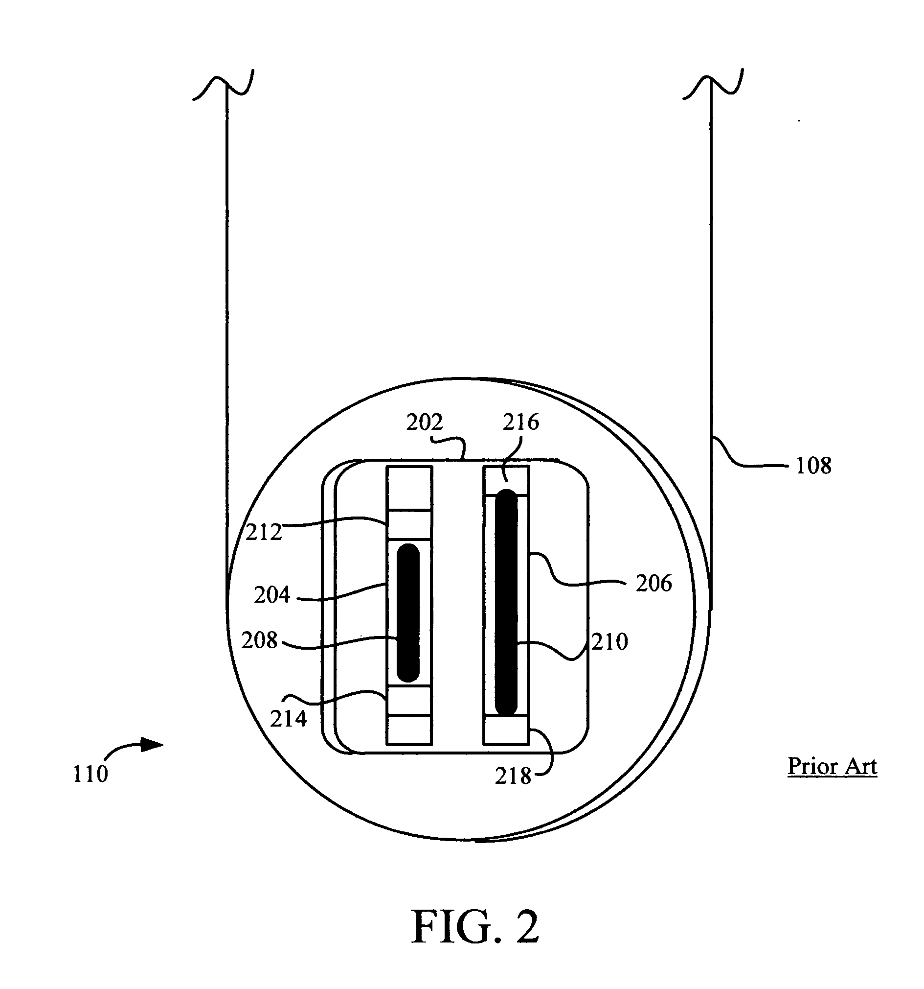
The use of tabs to alter the focal spot length is a common industry practice; However, the correct placement of the tabs in the channels is a very delicate, exact and time-consuming process.
Thus, using the tab adjustment process, inconsistencies in the performance of the X-ray tubes are inevitable.
However, the problem then arises as to how to adjust focal spot length without using tabs.
Additionally, with conventional cathode cup designs, a certain amount of focal spot distortion is present.
This distortion results in distortions in the images produced.

Method used


Image

  • Systems, apparatus and methods for x-ray imaging
  • Systems, apparatus and methods for x-ray imaging
  • Systems, apparatus and methods for x-ray imaging

Examples


Embodiment Construction

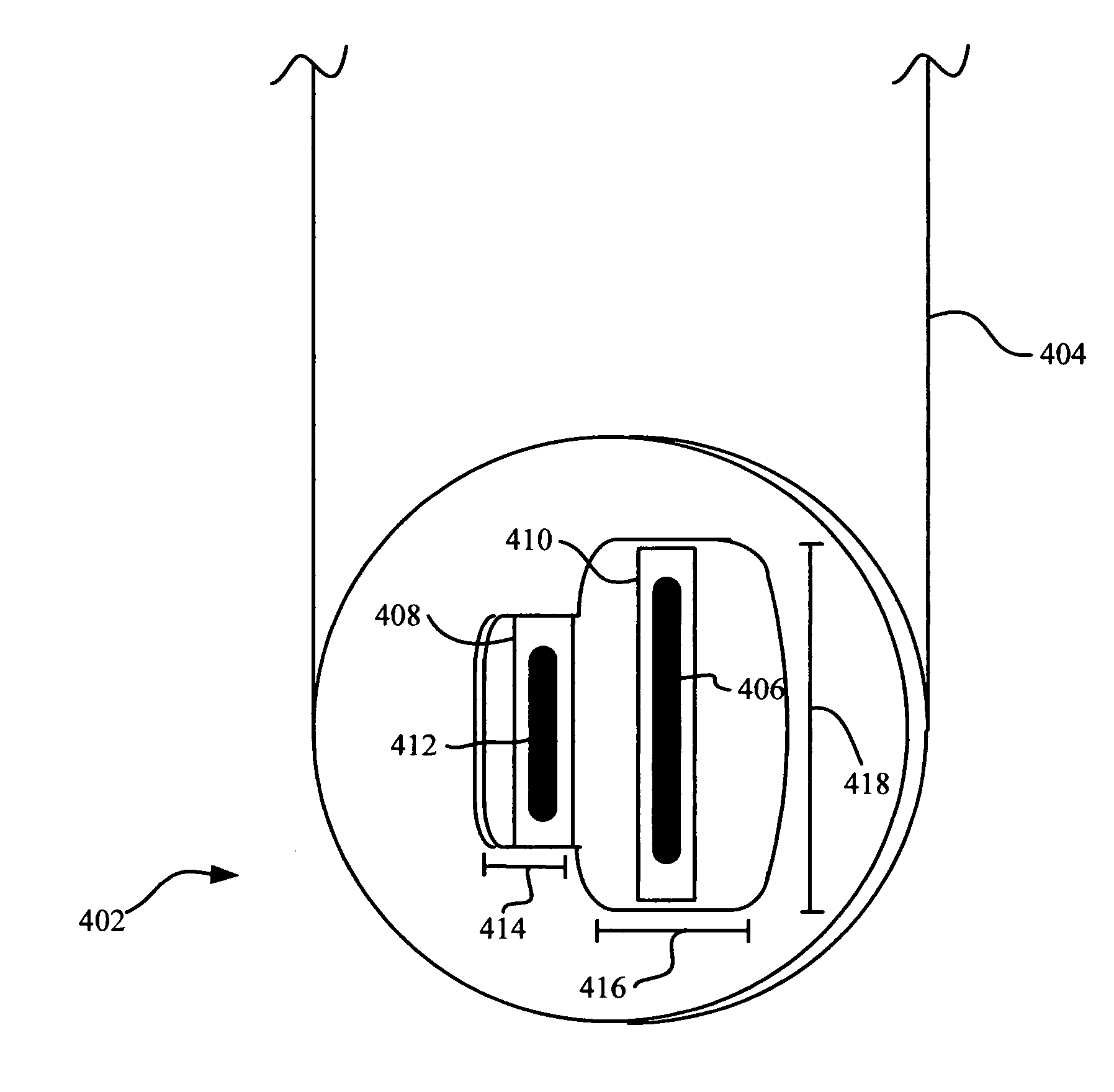
[0020] Accordingly, a cathode cup 402 is provided having a dual pocket design wherein a pocket is provided for each of the small filament and the large filament. Each pocket has a length that is tailored to a length of the filament therein. As such, the length of the focal spot produced by each filament can be adjusted by adjustments made to the length of the pockets, thus eliminating the need for tabs. Further, these adjustments to the pockets can be made during production of cathode cup 402, enhancing consistency. Also, a curved portion is included in the design of the pockets to accommodate for focal spot bending during imaging. As such, focal spot distortion is minimized, or eliminated.

[0021] Thus, the needs for tab-less focal spot length adjustment and for improved image quality are solved.

[0022] The detailed description is divided into four sections. In the first section, a conventional X-ray system and associated apparatus are described. In the second section, improved X-ra...


PUM


Abstract

A cathode cup is provided. The cathode cup includes one or more pockets; and one or more filaments associated with the one or more pockets. A same number of pockets as filaments are present. Each pocket is associated with exactly one filament and is configured to have a length that is tailored to a length of the filament. The cathode cup can be used in an X-ray system having an anode and a cathode. A method of electron beam shaping is provided. The method includes the following steps. A computer-simulated model of a cathode cup is created. The model is used to predict focal spot dimensions. The predicted focal spot dimensions are compared to desired focal spot dimensions. The steps of creating, using and comparing are repeated until the predicted focal spot dimensions match the desired focal spot dimensions. A cathode cup is created based on the computer-simulated model.

Description

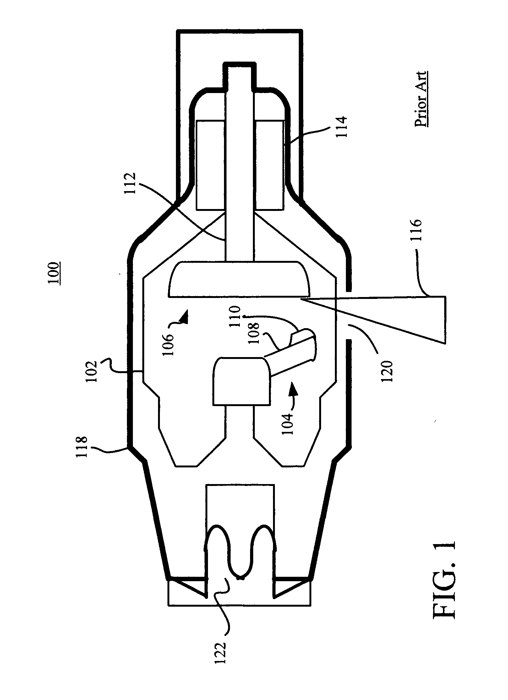
FIELD OF THE INVENTION [0001] This invention relates generally to X-ray imaging, and more particularly to cathode cup designs for enhancing X-ray image quality. BACKGROUND OF THE INVENTION [0002] X-ray systems are a commonly used medical imaging tool. X-ray systems include an X-ray tube having a cathode that acts as a negative electrode, and an anode, that acts as a positive electrode. The cathode and anode function in generating an X-ray beam that is used for imaging. Specifically, the cathode contains one or more filaments that, when subject to high voltage, release electrons via thermionic emission in the form of an electron beam. The number of filaments employed depends on the particular cathode design. The filaments are typically inset in channels of a cup structure that is part of the cathode, i.e., a cathode cup, that serves to focus the electron beam towards the anode. A portion of the electron beam impacting the anode is refracted off as an X-ray beam. [0003] The size of th...

Claims


Application Information

Patent Timeline
Patent Type & Authority Applications(United States)
IPC IPC(8): H01J35/06
CPCH01J35/06H01J2235/068H01J35/14H01J35/147H01J35/066
Inventor CHEN, JIZHONGLEMAITRE, SERGIOLOUNSBERRY, BRIAN DOUGLAS
Owner GENERAL ELECTRIC CO
Why Eureka
Try Eureka