Cosmic particle ignition of artificially ionized plasma patterns in the atmosphere

a technology of artificial ionization and plasma patterns, which is applied in the field of cosmic particle ignition of artificial ionized plasma patterns in the atmosphere, can solve the problems of high power requirements, high power requirements, and high cost involved, and achieve the effect of reducing the practical electric field of air breakdown, reducing power requirements, and facilitating the production of artificial ionized regions with inexpensive and available power sources

Inactive Publication Date: 2007-10-11
EASTLUND BERNARD
View PDF9 Cites 9 Cited by
  • Summary
  • Abstract
  • Description
  • Claims
  • Application Information

AI Technical Summary

Benefits of technology

[0013] This invention is a method and apparatus that lowers the practical electric field for air breakdown by a factor of up to 40 and lowers the power required for producing artificial ...

Problems solved by technology

Such systems would be extremely expensive to construct.
These high power requirements and the high cost involved has been a limitation on practical applications of artificial ionized regions of plasma...

Method used


Image

  • Cosmic particle ignition of artificially ionized plasma patterns in the atmosphere
  • Cosmic particle ignition of artificially ionized plasma patterns in the atmosphere
  • Cosmic particle ignition of artificially ionized plasma patterns in the atmosphere

Examples


Embodiment Construction

of the Method for Establishing a Plasma Pattern with Cosmic Particle Ignition

First Step—Establishment of Field Pattern

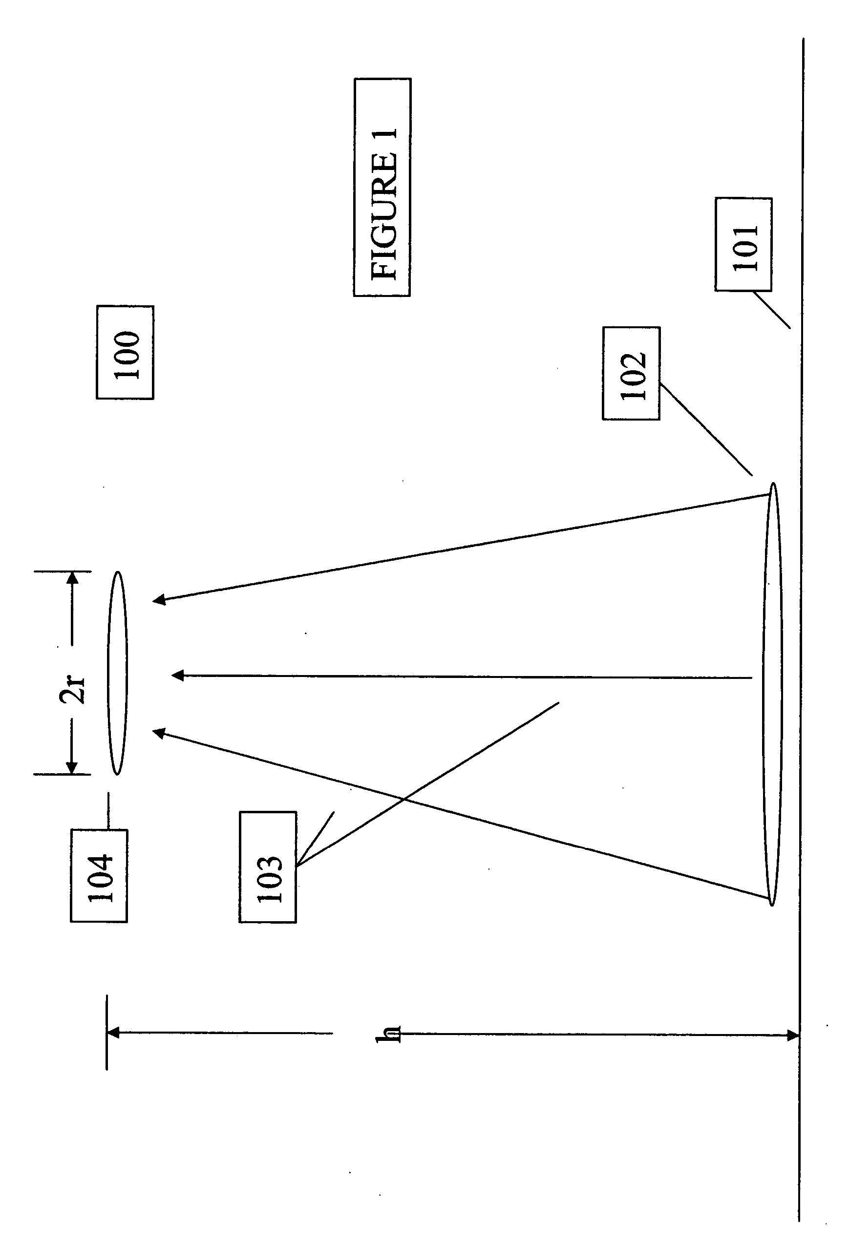
[0062]FIG. 1 is a schematic drawing of disc shaped field pattern 100 at an altitude h above the earth's surface. An electromagnetic wave radiator 102 beams electromagnetic waves in the electromagnetic wave propagation direction 103 to create a field pattern 104 which is a disc shaped pattern with a radius, r. The thickness of the disc shaped pattern 104 is initially on the order of many meters commensurate with the focal depth of the antenna pattern.

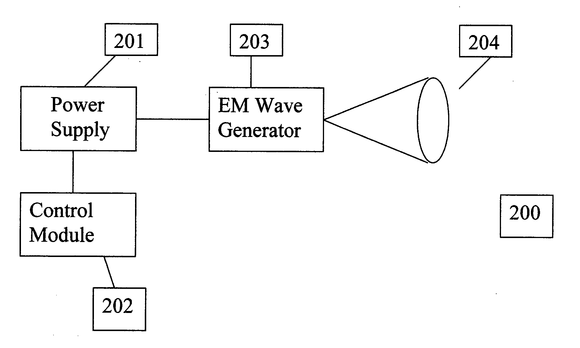
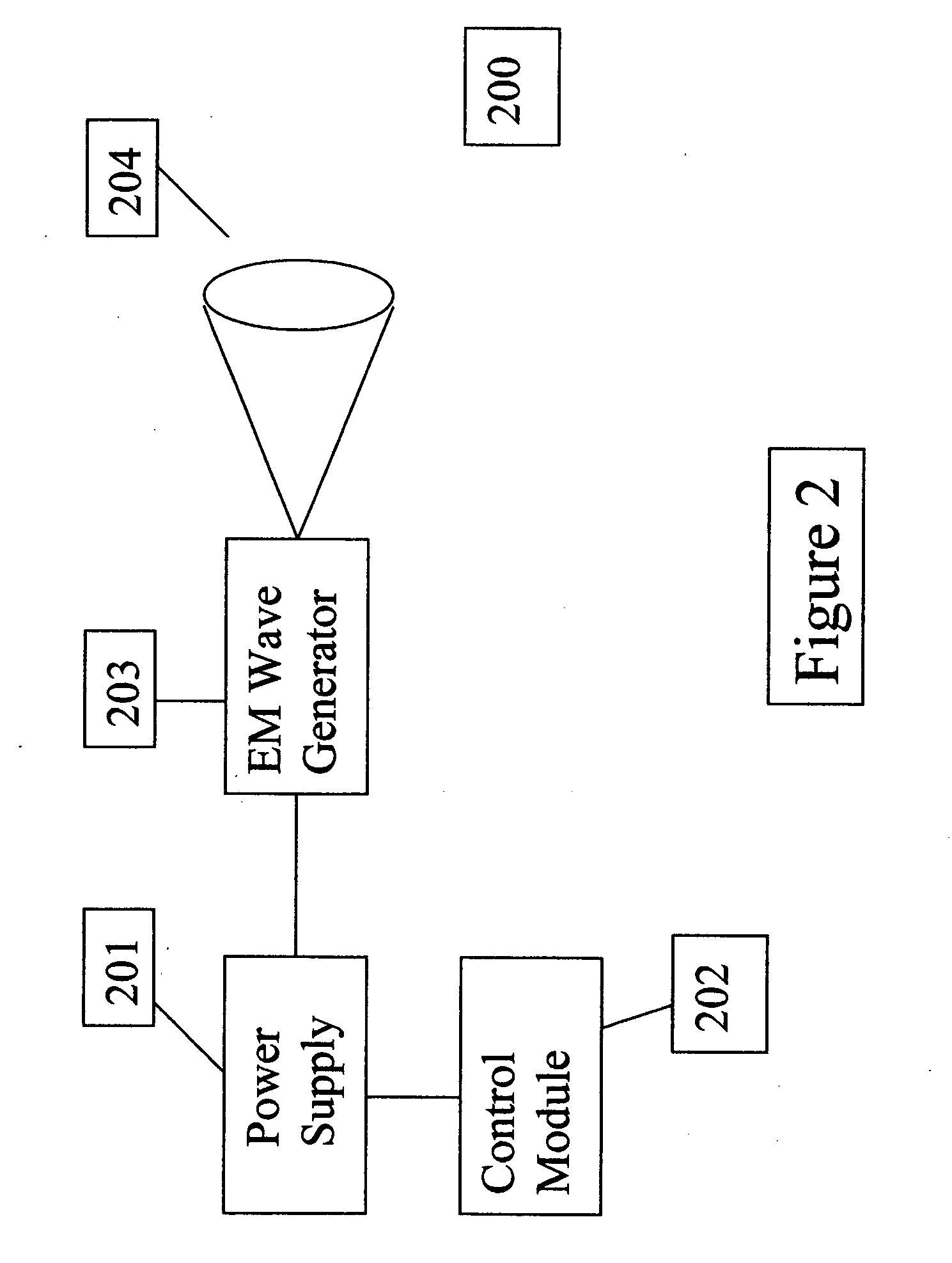
[0063]FIG. 2 is a block diagram of the system components of the electromagnetic wave radiator 102. It consists of a power supply 201, a control module 202 and electromagnetic wave generator 203 with a frequency ω and an antenna 204. The antenna can also be a phased array, with many separate radiating elements, a horn, a slot, or any other radiating geometry. The electromagnetic wave generator 203 can be a magnetron, kl...


PUM


Abstract

This invention is a method and apparatus for creating artificially ionized regions in the atmosphere utilizing ionization trails of cosmic rays and micro-meteors to ignite plasma patterns in electric field patterns formed by ground based electromagnetic wave radiators. The applications are useful for telecommunications, weather control, lightening protection and defense applications. The invention lowers the power requirements for forming artificial ionized regions in the atmosphere by a factor of up to 1600 times lower than those required in existing designs and projections for creation of artificial ionized regions in the atmosphere.

Description

BACKGROUND OF THE INVENTION [0001] 1. Field of Invention [0002] This invention generally relates to generation of artificially ionized plasma patterns in the atmosphere and to lowering the cost and enhancing the reliability of applications such as telecommunications systems. [0003] 2. Prior Art [0004] Various methods and apparatus have been suggested for creation of localized regions of ionized gas in the atmosphere for the purpose of communications enhancements and other purposes. In particular, Eastlund in U.S. Pat. Nos. 4,712,155, 4,686,605 and 5,038,664 suggested creation of an artificial ionospheric mirror using electron cyclotron resonance heating from directed electromagnetic waves of 1 to 10 Mhz from a large phased array antenna located in Alaska. The power level required for such an operation was very large, over a billion watts. [0005] Subsequent work by ARCO's then subsidiary APTI resulted in studies of the details of creation of such an ionized layer with a single phased...

Claims


Application Information

Patent Timeline
IPC IPC(8): H01L21/336
CPCA01G15/00
Inventor EASTLUND, BERNARD
Owner EASTLUND BERNARD
Why Eureka
Try Eureka