Rod or tube lifting apparatus

a technology of lifting apparatus and rod or tube, which is applied in the direction of mechanical equipment, drilling pipes, screw threaded joints, etc., can solve the problems of personnel in harm's way, prone to injury, and prone to tripping operations

Active Publication Date: 2022-02-01
KAUS BOREALIS PTY LTD
View PDF14 Cites 0 Cited by
  • Summary
  • Abstract
  • Description
  • Claims
  • Application Information

AI Technical Summary

Benefits of technology

[0007]Applying a locking force in the axial direction of the tube or rod may eliminate the need to apply substantial torque to engage the apparatus with the tube or rod. The locking force may be equivalent to a torque approximately required to pre-load a joint formed between the engagement member and engagement portion. Generally, the pre-load torque is specified by a manufacturer of the tube or rod. The locking force, therefore, is determined by the type of tube or rod and the associated pre-load torque required. By pre-load, it is meant the torque applied to a joint formed between the engagement member and engagement portion before a load of the associated string is applied to the joint. Any use herein of the term “torque” is therefore to be taken to mean the pre-load torque unless the context clearly indicates it to be otherwise.
[0010]In existing setups, applying such torques generally requires specialised machinery. Further, when operators are required to operate machinery, such as power tongs, to apply such torque, they can be exposed to hazardous working practices. Therefore, using an abutment member to apply the locking force may reduce hazardous working practices when moving tube or rod. Further, applying the apparatus to the tube or rod may eliminate the requirement to use elevators to engage the tube or rod (i.e. for raising or lowering the tube or rod) thereby removing exposure to operating elevators for this particular operation.
[0014]In an embodiment, the first thread is on a female portion of the apparatus and the second thread is on a corresponding male portion of the tube or rod, or vice versa. In this way, the apparatus may be able to connect to tube or rod being in the “pin up” or “box up” orientation. In the pin up orientation, the tube or rod has the engagement portion on the male (outside) surface, whereas in the box up orientation that tube or rod has the engagement portion on the female (inside) surface. Having the apparatus being able to connect to rod in a pin up or box up orientation may allow the apparatus to be used on a wide variety of tube or rod.
[0018]The abutment member may also be adapted to apply a radial compressive force. The compressive force may be provided by an auxiliary abutment member associated with the abutment member. The abutment member and / or auxiliary abutment member may have complementary tapered surfaces. Therefore, movement of the abutment member and / or the auxiliary abutment member in the form of a compression sleeve may provide the compressive force. Providing a compressive force in addition to the locking force may help to further secure the engagement member to the engagement portion.
[0037]The engagement member may engage the engagement portion by rotational engagement. For example, the engagement member may be screwed onto the engagement portion. The term “onto” is to be interpreted broadly to mean the engagement member can be screwed onto an outer surface of the engagement portion (i.e. pin up orientation) or can be screwed onto an inner surface of the engagement portion (i.e. box up orientation). The method may be performed using a drill rig, a workover rig, a flushby rig or a data gathering rig. In this way, the apparatus may be moved in a vertical direction using a drill line (e.g. wire rope) associated with the rig. The apparatus may connect and / or disconnect to tube or rod located on a catwalk or other structure of the rig. Connection and / or disconnection to tube or rod on the catwalk may be automated. The apparatus may connect to a drill string associated with the rig. Connection with the drill string may also be automated. In this way, the method may not require any hands-on operator input. The apparatus and / or method may thus provide a hands-free way of making and breaking a drill string.

Problems solved by technology

Currently tripping operations are typically not hands-free.
Breaking and spinning off the rod, pipe, tube or casing from the string can place the rig personnel in harm's way, and can lead to injuries which can be fatal.

Method used


Image

  • Rod or tube lifting apparatus
  • Rod or tube lifting apparatus
  • Rod or tube lifting apparatus

Examples


Embodiment Construction

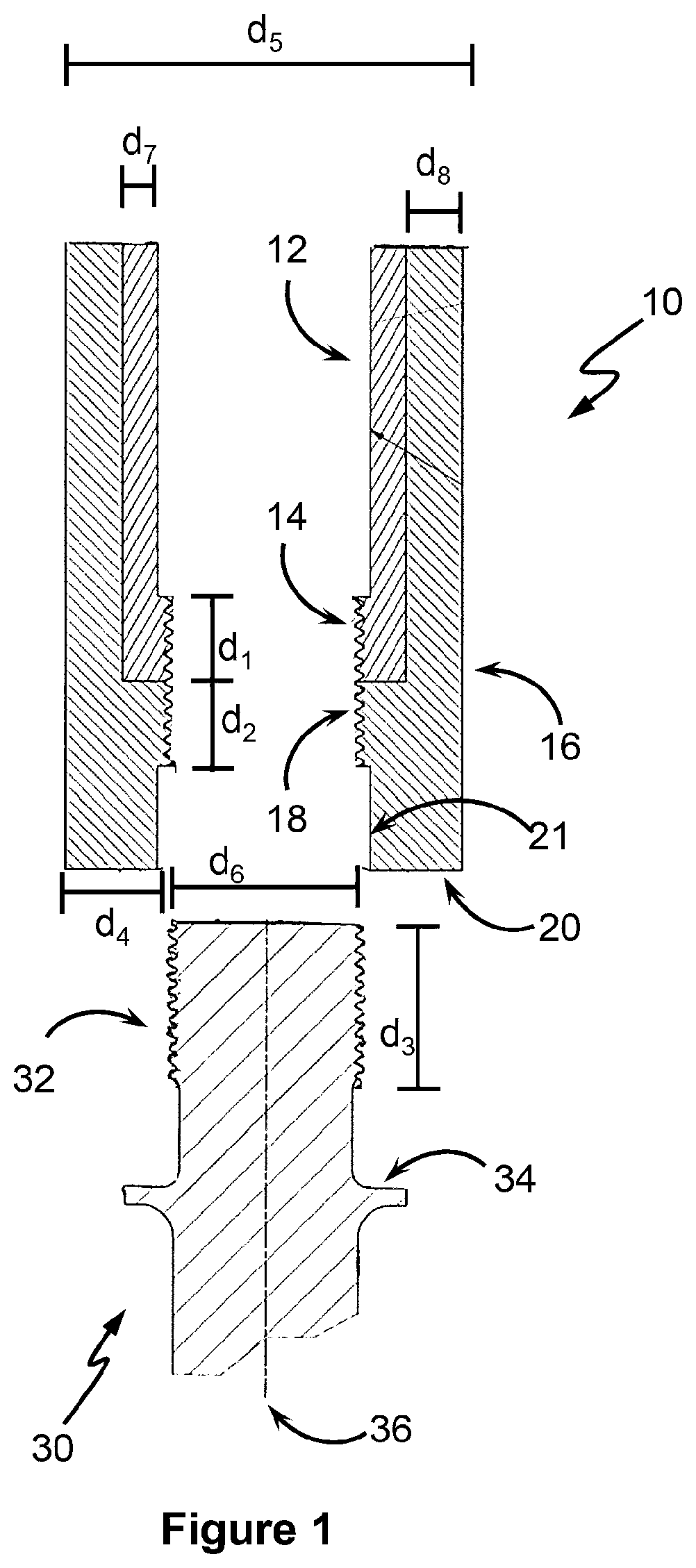
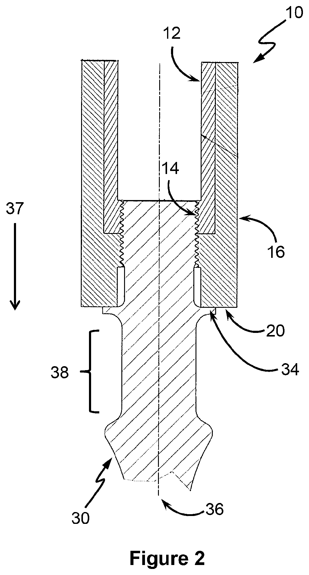
[0049]FIGS. 1 and 2 show a first embodiment of an apparatus 10. The apparatus 10 can be employed for lifting rod or tube and the like, such as when servicing and in the drilling of wells (e.g. oil and gas wells, etc.). The tube or rod can be anywhere from ¼″ (e.g. sucker rod) to 12″ (e.g. well casing) in diameter.

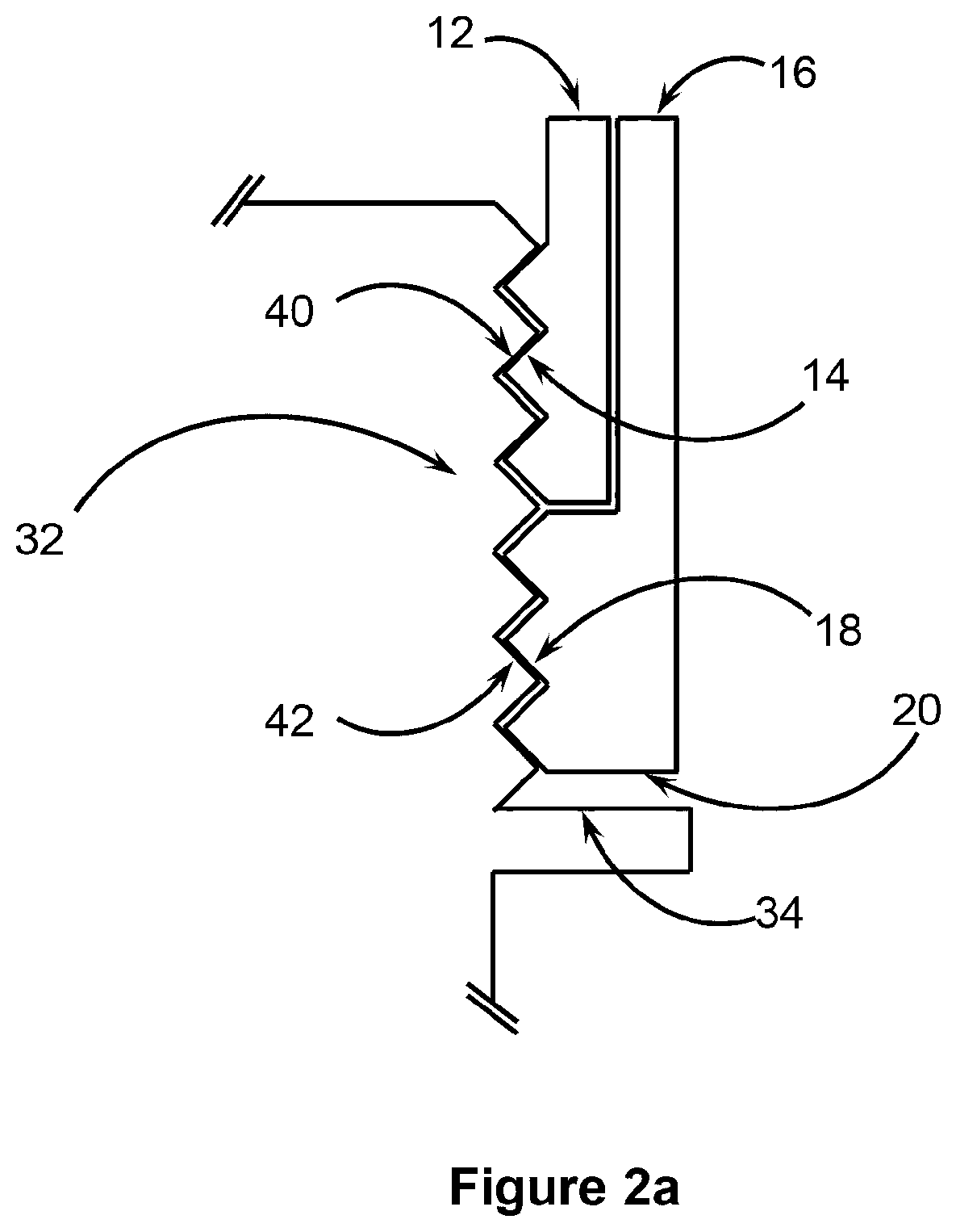
[0050]Apparatus 10 has an engagement member in the form of an inner sleeve 12, and an abutment member in a form of an outer sleeve 16 associated with the inner sleeve 12. In the embodiment of FIGS. 1 and 2, the outer sleeve 16 sleeves the inner sleeve 12 so as to be coaxially arranged thereto (i.e. having a common axis). Outer sleeve 16 is also moveable along the common axis (i.e. moveable in the direction of arrow 37) relative to the inner sleeve 12. The outer sleeve 16 also has an internally threaded region 18, which region 18 continues as an internal threaded region 14 of the inner sleeve 12. In this way, threaded region 14 and 18 forms a continuous thread. Bearings and / ...


PUM


Abstract

Disclosed is an apparatus for connecting to a tube or a rod in a longitudinal axial direction of the tube or rod. The tube or rod is used in the assembly of a tube or rod string. The apparatus comprises an engagement member adapted to engage with an engagement 5 portion located at an end of the tube or rod. The apparatus also comprises an abutment member associated with the engagement member. The abutment member is adapted to abut an abutment portion of the tube or rod. The apparatus is adapted such that, when the engagement member is engaged with the engagement portion and the abutment member abuts the abutment portion, the abutment member can apply a locking force to the abutment 0 portion in the axial direction of the tube or rod, being a force that secures the engagement member to the engagement portion such that the tube or rod can be lifted and moved.

Description

TECHNICAL FIELD[0001]This disclosure generally relates to apparatus and methods for lifting rod or tube. The apparatus and methods find particular, though not exclusive, application in the servicing and drilling of wells such as for oil and gas.BACKGROUND ART[0002]A number of specialised pieces of equipment are used for lifting rod, pipe tube and casing to and from wells, in and out of wells, and in the making or breaking of rod strings. These specialised pieces of equipment include elevators of various types including sucker rod elevators, tube elevators, rod elevators, pipe elevators casing elevators, double / centre latch drill pipe elevators and side door elevators. The elevators are used for raising and lowering the string in the well and for adding or removing rod, tube or casing to the string. Power tongs are typically used for spinning and make & break functions to connect and disconnect the rod, pipe, tube, casing to and from the string. Generally, elevators are configured to...

Claims


Application Information

Patent Timeline
Patent Type & Authority Patents(United States)
IPC IPC(8): E21B19/06E21B17/042E21B19/16E21B17/046F16L15/08E21B3/02
CPCE21B19/06E21B3/02E21B17/042E21B17/046E21B19/16F16L15/08
Inventor HESELTINE, HYLTON ANDREW
Owner KAUS BOREALIS PTY LTD
Why Eureka
Try Eureka