Electrolytic copper plating process

a technology of electrolytic copper plating and copper plating film, which is applied in the direction of electrolytic processes, electrolysis components, printed circuit manufacturing, etc., can solve the problems of not being suited to practical use, taking an unduly long time for the full oxidative decomposition of decomposed/modified organic products, and failing to obtain copper plating films or copper plating fills as desired

Active Publication Date: 2011-02-22
C UYEMURA & CO LTD
View PDF10 Cites 1 Cited by
  • Summary
  • Abstract
  • Description
  • Claims
  • Application Information

AI Technical Summary

Benefits of technology

[0011]With the foregoing circumstances in view, the present invention has as an object thereof the provision of an electrolytic copper plating process, which upon applying electrolytic copper plating to workpieces having structural features to be filled with copper plating such as printed circuit boards or wafers having blind vias and / or trenches, can perform efficient oxidative decomposition of decomposed / modified organic products to be formed as a result of oxidation or reduction of organic additives in the course of continuous electroplating in a copper sulfate plating bath, can reduce, to a practical minimum level, defective copper plating, voids and the like to be caused by the decomposed / modified organic products, and can stably perform plating over a long term while maintaining high productivity.
[0012]The present inventor has enthusiastically conducted an investigation to overcome the above-described problems. As a result, it was found that the amount of decomposed / modified organic products of organic additives basically tend to increase with the bath current density (A / L), and it was also found control in a plating tank is effective against effects of the decomposed / modified organic products on plating. It was then found that by controlling the environment inside a plating tank in which electrolytic copper plating is being performed, specifically by immersing metal copper in an unpowered state in a copper sulfate plating bath in the same tank as a plating tank with an anode and cathodes (workpieces) immersed therein, applying air bubbling to the metal copper, and upon application of the air bubbling, controlling the rate of the air bubbling at a predetermined level such that decomposed / modified organic products in the copper sulfate plating bath in the plating tank are efficiently subjected to oxidative decomposition while maintaining a predetermined plating rate, defective copper plating fill, voids and the like to be caused by such decomposed / modified organic products can be reduced to a practical minimum level and plating can be stably performed over a long term, leading to the completion of the present invention.
[0022]When workpieces having structural features to be filled with copper plating to form wirings (including interlayer connection wirings), such as printed circuit boards or wafers having blind vias, trenches and / or interposer holes, are continuously electroplated using a copper sulfate plating bath, organic substances (decomposed / modified organic products) are considered to occur as a result of oxidation or reduction of organic additives as described above. According to the present invention, these decomposed / modified organic products can be efficiently subjected to oxidative decomposition, thereby making it possible to reduce defective copper plating fill, voids and the like, which are to be caused by such decomposed / modified organic products, to a practical minimum level and also to stably perform electrolytic copper plating over a long term without stopping a plating line.

Problems solved by technology

It is, however, known that in the course of continuous plating, these organic additives may be decomposed or modified to result in a failure in obtaining copper plating films or copper plating fills as desired.
When plating is continuously performed, however, it takes an unduly long time for the full oxidative decomposition of decomposed / modified organic products.
This technology is, therefore, not suited for practical use.
With air agitation alone, however, the oxidative decomposition of decomposed / modified organic products is insufficient.
However, stronger air agitation result in more return of large bubbles to the plating bath.
When such large bubbles mix into the plating tank, they adhere to workpieces and cause plating defects such as bare spots.
Further, the dissolved oxygen in the plating bath also decomposes organic additives as mentioned above.
An excessive increase in the quantity of dissolved oxygen in the plating bath, therefore, leads to greater formation of undesired organic substances.
As a consequence, defective copper plating fill and / or defective plating films is induced, and moreover, more organic additives have to be replenished.
This technology is, therefore, uneconomical.
This technology is, however, uneconomical because a great deal of metal copper has to be arranged to effect the decomposition.
In addition, this technology applies air agitation to the metal copper, and therefore, is accompanied by the same problem as the above-described technology of Japanese Patent Laid-open No. 2004-143478.

Method used


Image

  • Electrolytic copper plating process
  • Electrolytic copper plating process
  • Electrolytic copper plating process

Examples


example 1

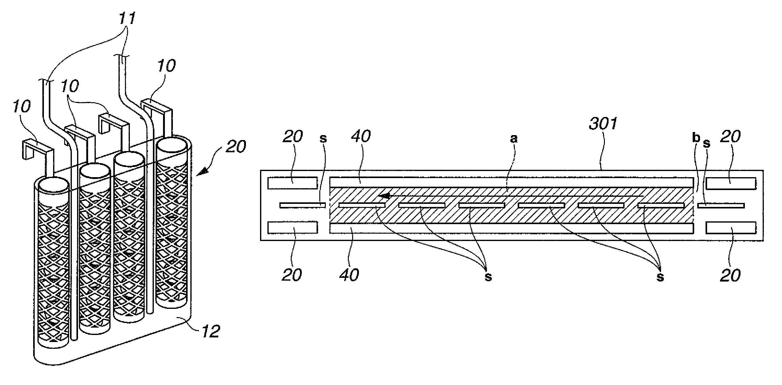
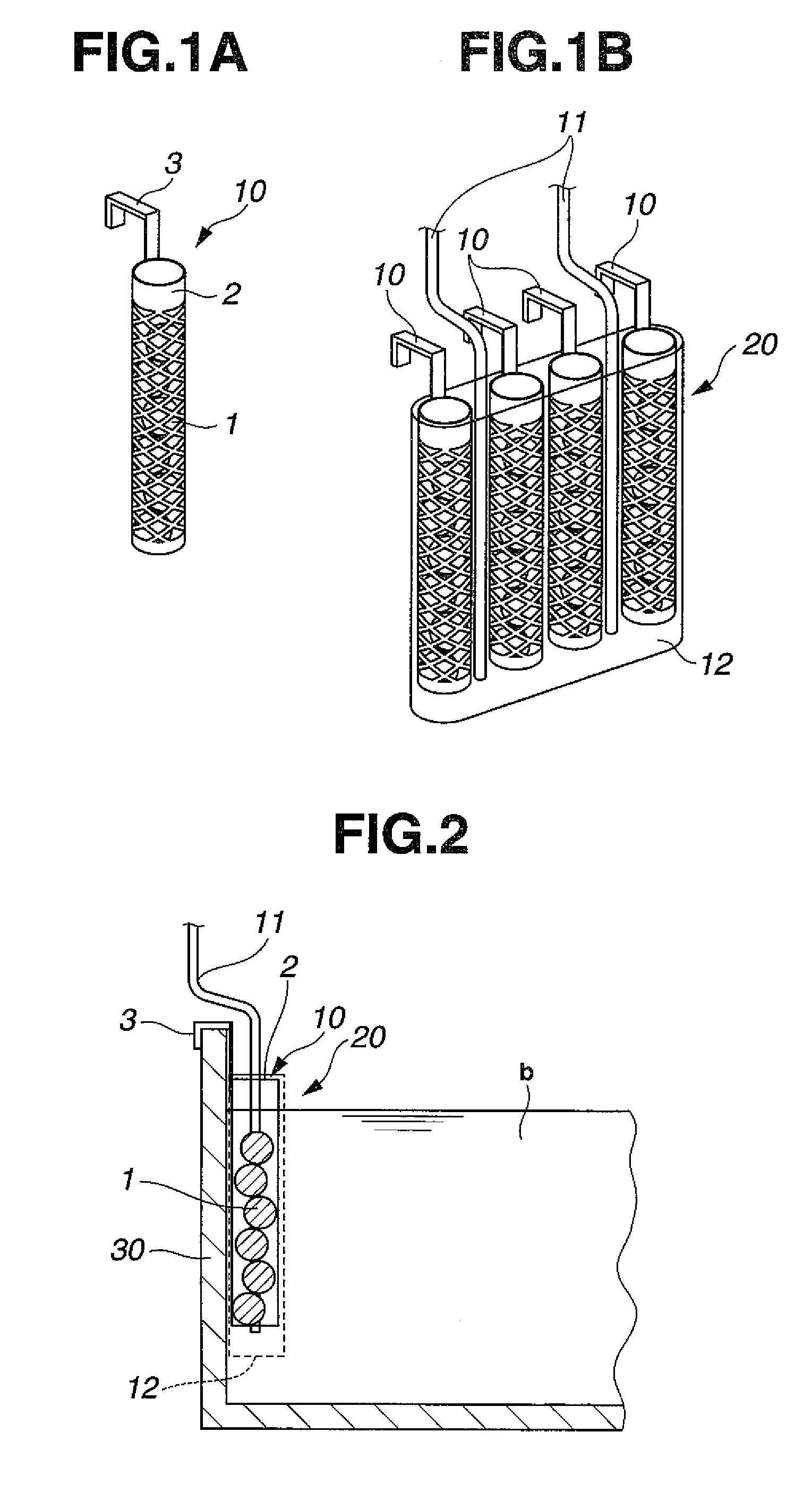
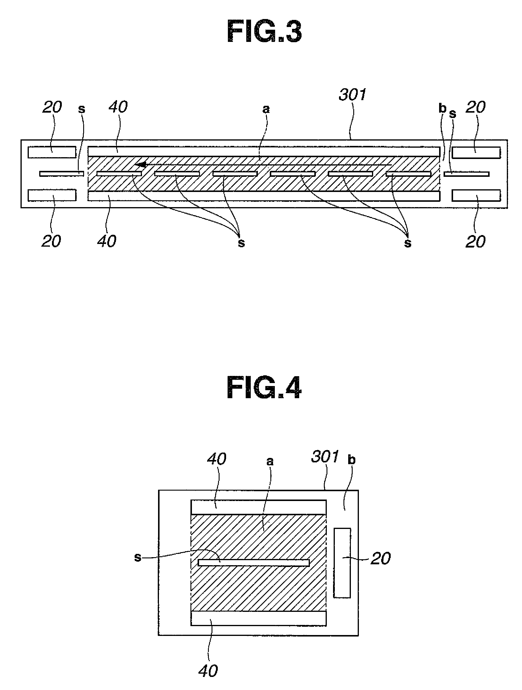
[0060]As workpieces to be plated, printed circuit boards having blind vias of 80 μm diameter and 35 μm depth were provided. After conventionally-known pretreatment, catalyst treatment and chemical copper plating were applied to the printed circuit boards, electrolytic copper plating was continuously applied under the below-described conditions for running plating in the below-described copper sulfate plating bath by changing the circuit boards one after one. As oxidative decomposition units, unit similar to that shown in FIG. 1B were used by arranging them at the positions depicted in FIG. 3. During the electrolytic copper plating, various components were measured by known concentration analysis methods. Copper ions were replenished by dissolving copper oxide in the separate tank 50 shown in FIG. 7 and circulating the plating bath to the plating tank 30 by a pump, and other components were replenished to the overflow tank 302 as much as needed. In the electrolytic copper plating bat...

example 2

[0066]Electrolytic copper plating was performed in a similar manner as in Example 1 except that the anode was changed to a soluble anode (phosphorus-containing copper balls held in a Ti-made basket and covered by a polypropylene-made bag). Plating fillability for blind vias was assessed as in Example 1. The results are presented in Table 1.

examples 3 to 5

[0072]Electrolytic copper plating was performed in a similar manner as in Example 1 except that the bath current density (in those examples, the plated area was not fixed at 50 dm2 but the bath current density was used as an index) and the total immersed area of metal copper and the air bubbling rate were changed as presented in Table 2. Plating fillability for blind vias was assessed as in Example 1. The results are presented in Table 2.


PUM

PropertyMeasurementUnit
current densityaaaaaaaaaa
pHaaaaaaaaaa
current densityaaaaaaaaaa

Abstract

Disclosed herein is an electrolytic copper plating process for electroplating copper on workpieces in a copper sulfate plating bath filled in a plating tank and containing an organic additive while using a soluble anode or insoluble anode as an anode and the workpieces as cathodes, including the steps of, setting a bath current density at not higher than 5 A / L, immersing metal copper in a region of the copper sulfate plating bath, the region being apart from a region between the anode and the cathode and also from regions adjacent the anode and cathode, respectively, such that a neighborhood of the thus-immersed metal copper can be used as an oxidative decomposition region, setting an immersed area of the metal copper at not smaller than 0.001 dm2 / L based on the plating bath, and applying air bubbling to the oxidative decomposition region at not lower than 0.01 L / dm2·min based on the immersed area.

Description

CROSS-REFERENCE TO RELATED APPLICATION[0001]This non-provisional application claims priority under 35 U.S.C. §119(a) on Patent Application No. 2007-207440 filed in Japan on Aug. 9, 2007, the entire contents of which are hereby incorporated by reference.BACKGROUND OF THE INVENTION[0002]1. Field of the Invention[0003]This invention relates to a process for electrolytically copper-plating workpieces in a copper sulfate plating bath.[0004]2. Description of the Related Art[0005]Upon forming a pattern on printed circuit boards or wafers, copper sulfate electroplating is applied using an insoluble anode or soluble anode. In a copper sulfate plating bath for the printed circuit boards or wafers, organic additives called a “brightener”, “leveler”, “promoter”, “inhibitor” and / or the like are contained. It is, however, known that in the course of continuous plating, these organic additives may be decomposed or modified to result in a failure in obtaining copper plating films or copper plating ...

Claims


Application Information

Patent Timeline
Patent Type & Authority Patents(United States)
IPC IPC(8): C25D21/18C25D3/38
CPCC25D3/38C25D21/16H05K3/241C25D5/003C25D17/12
Inventor TACHIBANA, SHINJIKAWASE, TOMOHIROOMURA, NAOYUKIISONO, TOSHIHISASHIMIZU, KOJI
Owner C UYEMURA & CO LTD
Why Eureka
Try Eureka