Permanent magnet dynamoelectric machine with axially displaceable permanent magnet rotor assembly

a permanent magnet, dynamoelectric machine technology, applied in the direction of magnetic circuit rotating parts, magnetic circuit shape/form/construction, windings, etc., can solve the problems of power source not being able to supply additional potential, the output torque of the dynamoelectric machine is falling with increasing speed, and the convenience of regulating the generated electrical potential

Inactive Publication Date: 2007-10-18
HAMILTON SUNDSTRAND CORP
View PDF10 Cites 53 Cited by
  • Summary
  • Abstract
  • Description
  • Claims
  • Application Information

AI Technical Summary

Benefits of technology

[0024]FIG. 17 is a cut-away side view of the dynamoelectric machine of FIGS. 15 and 16 that shows the rotor assembly with its rotor magnets fully displaced from axial alignment with the stator poles in the stator assembly.
[0025]FIG. 18 is a cut-away side view of a permanent magnet type dynamoelectric machine of the “inside out” type according to an eighth possible embodiment of the invention that shows a rotor assembly with rotor magnets in axial alignment with stator poles in a stator assembly.
[0026]FIG. 19 is a cut-away side view of a permanent magnet type dynamoelectric machine of the conventional type according to a ninth possible embodiment of the invention that shows a rotor assembly with rotor magnets in axial alignment with s...

Problems solved by technology

As a generator, a primary problem with this class of machines is that there is no convenient way to regulate the generated electrical potential that may vary with rotational speed and load variations, unlike dynamoelectric machines with a rotor winding that may control rotor winding current from an exciter for regulation.
Eventually, the power source cannot supply additional potential and then the output torque of the dynamoelectric machine falls with increasing speed until no further torque is achievable.
As a motor, a primary problem with this class of machines is that there is no convenient way to regulate the generated back EMF that increases with rotational speed, unlike dynamoelectric machines with a rotor winding that may control rotor winding current from an exciter to reduce back EMF at hi...

Method used


Image

  • Permanent magnet dynamoelectric machine with axially displaceable permanent magnet rotor assembly
  • Permanent magnet dynamoelectric machine with axially displaceable permanent magnet rotor assembly
  • Permanent magnet dynamoelectric machine with axially displaceable permanent magnet rotor assembly

Examples


Embodiment Construction

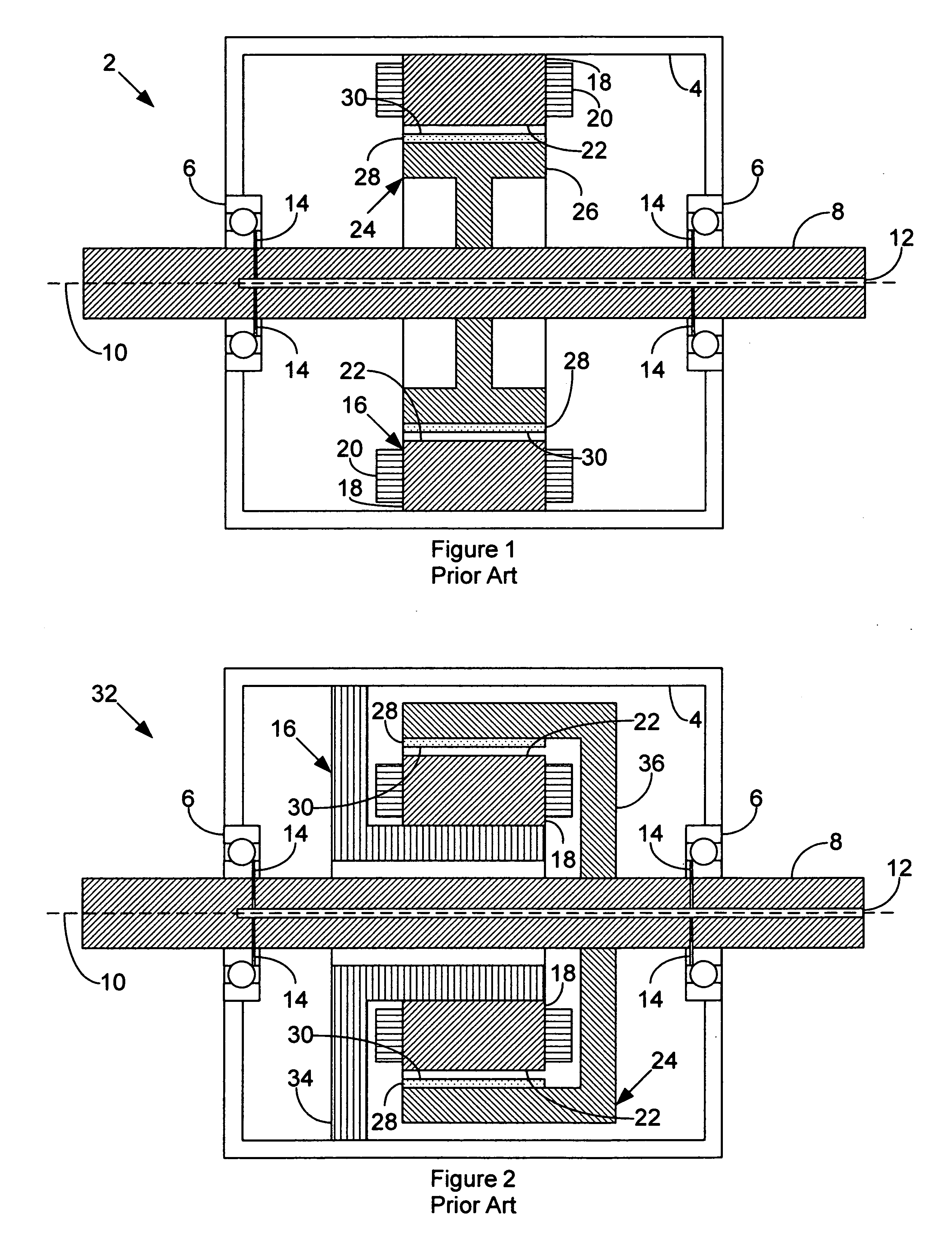
[0030]FIG. 1 is a cut-away side view of a permanent magnet type dynamoelectric machine 2 of the conventional type according to the prior art. The dynamoelectric machine 2 comprises a housing 4 that mounts at least one bearing assembly 6 for supporting a drive shaft 8 that has a drive shaft axis of rotation 10. Two bearing assemblies 6 support the drive shaft 8 in FIG. 1. For high power applications, the drive shaft 8 may have a drive shaft lubrication oil channel 12 that extends from one end of the drive shaft 8 down along the drive shaft axis 10 for receiving lubrication oil and distributing it to each bearing assembly 6 by way of bearing lubrication channels 14 that couple to the drive shaft lubrication oil channel 12.

[0031] The dynamoelectric machine 2 also comprises a stator assembly 16 mounted to the housing 4 that comprises a plurality of stator poles 18. Each stator pole 18 has an associated stator pole winding 20. The stator poles 18 have pole faces 22 arranged in a general...


PUM


Abstract

A dynamoelectric machine comprises: a stator that comprises a plurality of stator poles arranged around a stator surface of revolution with a stator axis for the stator surface of revolution; at least one rotor that comprises a plurality of permanent rotor magnets arranged around a rotor surface of revolution with a rotor axis for the rotor surface of revolution that is coincident with the stator axis and with the rotor surface of revolution adjacent the stator surface of revolution; a drive shaft with a drive shaft axis of rotation that is substantially coincident with the stator axis coupled to the rotor for rotating the rotor relative to the stator about the drive shaft axis of rotation; and a at least one actuator for axially displacing the rotor surface of revolution along the drive shaft relative to the stator surface of revolution to change magnetic flux interaction between the stator poles and the rotor magnets; wherein at least one of the surfaces of revolution tilts with respect to the drive shaft axis of rotation.

Description

FIELD OF THE INVENTION [0001] The invention relates to dynamoelectric machines of the permanent magnet type, and more particularly to a permanent magnet dynamoelectric machine that has adjustable magnetic flux interaction between its rotor and its stator. BACKGROUND OF THE INVENTION [0002] Dynamoelectric machines of the permanent magnet type have a rotor assembly comprising a plurality of permanent rotor magnets arranged radially around a drive shaft that rotate with the drive shaft about a stator assembly that comprises a plurality of stator poles and a stator winding. The rotor magnets have a fixed axial alignment that generally coincides with the axial position of the stator poles. The rotor magnets have a fixed radial alignment that is inside the radial position of the stator poles for machines of the conventional type or outside the radial position of the stator poles for machines of the “inside out” type. [0003] Since the rotor magnets have a fixed radial and axial alignment w...

Claims


Application Information

Patent Timeline
IPC IPC(8): H02K23/46H02K21/00H02K1/22
CPCH02K21/027H02K16/02
Inventor HIMMELMANN, RICHARD A.SHAHAMAT, MOHAMMADHALSEY, DAVID G.
Owner HAMILTON SUNDSTRAND CORP
Why Eureka
Try Eureka