Base member for liquid discharge head, liquid discharge head utilizing the same, and producing method therefor

a technology of liquid discharge head and base member, which is applied in the direction of printing, etc., can solve the problems of resinous material and the base member becoming liable to peel at the surface, unable to precisely form the discharge port of a small area, and deformation of the ink discharge port, etc., to achieve high precision and high reliability

Inactive Publication Date: 2007-10-18
CANON KK
View PDF10 Cites 7 Cited by
  • Summary
  • Abstract
  • Description
  • Claims
  • Application Information

AI Technical Summary

Benefits of technology

[0011] An object of the present invention is to provide a base member for a liquid discharge head, in which an internal surface of a liquid flow path and a discharge port are prevented from swelling by a liquid and are formed with a high precision and a high reliability, a liquid discharge head utilizing such base member and producing methods therefor.
[0013] Still another object of the present invention is to provide a producing method for a base member for liquid discharge head, including a base member, an energy generating element for discharging a liquid, formed on the base member, and a resin structure having a liquid discharge port for discharging the liquid and disposed on the base member so as to cover the energy generating element, the producing method including steps of forming a mold member in an area on the base member where a flow path is to be formed later, forming the resin structure so as to cover the mold member, forming a discharge port aperture protective layer which protects a surface of the resin structure where the liquid discharge port is formed by a catalytic chemical vapor deposition, forming an aperture in the discharge port aperture protective layer and in the resin structure from a position for forming the liquid discharge port to the mold member, and removing the mold member thereby forming the liquid path in the interior of the resin structure.

Problems solved by technology

H06-286149, the resinous material may exhibit a swelling by the ink or the like, thereby causing a deformation of the ink discharge port.
Also the resinous material and the base member may become liable to show a peeling at the surface of the base member, resulting from the aforementioned deformation of the resinous material by the ink or from a deterioration caused by a chemical reaction with the ink component itself.
Also the flow path forming member, being formed by a photosensitive resin material, may cause a deformation by an unevenness in the exposure or by a reflection from an underlying layer, thereby becoming unable to precisely form the discharge port of a small area, corresponding to a small liquid droplet.

Method used


Image

  • Base member for liquid discharge head, liquid discharge head utilizing the same, and producing method therefor
  • Base member for liquid discharge head, liquid discharge head utilizing the same, and producing method therefor
  • Base member for liquid discharge head, liquid discharge head utilizing the same, and producing method therefor

Examples


first embodiment

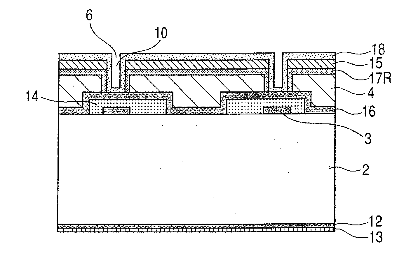
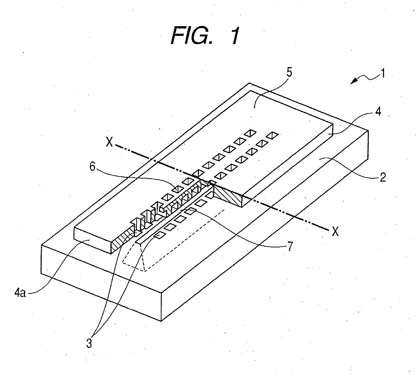
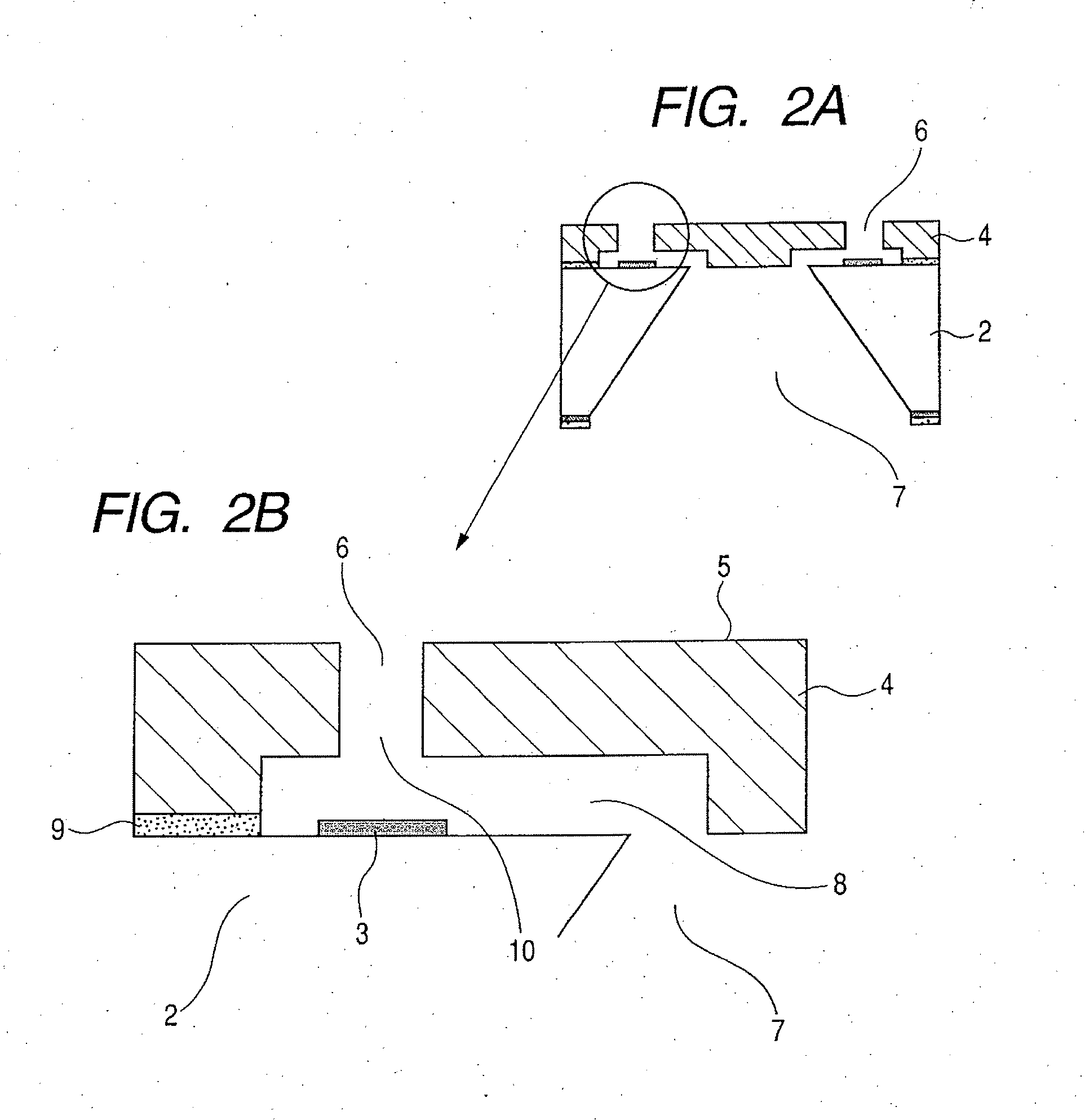
[0068] The discharge port-containing face 5 of the ink jet head is preferably subjected to a water-repellent treatment, and in fact has been subjected to a water-repellent treatment in practice. In the following exemplary embodiment, the formation of protective layer by the Cat-CVD process is most effective, and there will be described the formation of the protective layer by the Cat-CVD process on the discharge port-containing face 5, corresponding to (1) above.

[0069] The producing method described herein include following steps of: forming a mold member in an area on the base member where the flow path is to be formed later; forming a resin structure so as to cover the mold member; forming, on a face of the resin structure where a liquid discharge port is to be formed, a discharge port-containing face protective layer to be described later by the Cat-CVD process; forming an aperture in the discharge port-containing face protective layer and the resin structure, extending from a p...

second exemplary embodiment

[0102] In the following exemplary embodiment, there will be described a producing method for forming protective layers in the aforementioned portions (1) to (4) by the Cat-CVD process, utilizing the schematic cross-sectional views in FIGS. 8A, 8B, 8C, 8D, 8E, 8F, 8G, 8H, 8I, 8J and 8K illustrating the respective process steps.

[0103] The producing method described here includes following process steps of: forming a mold member in an area of the base member in which a flow path is to be formed; forming, on the base member by the Cat-CVD process, a flow path internal surface protective layer (details being described later) which covers the mold member and constitutes a layer for protecting the internal surface of the flow path, and an interface protective layer (details being described later) which protects an interface of the base member and the resin structure; forming, on the flow path internal surface protective layer and the interface protective layer, a resin structure covering ...

third exemplary embodiment

[0128] In the following exemplary embodiment, there will be described a producing method for forming protective layers in the aforementioned portions (1) to (4) by the Cat-CVD process, utilizing the schematic cross-sectional views in FIGS. 9A, 9B, 9C, 9D, 9E,9F, 9G, 9H, 9I, 9J and 9K illustrating the respective process steps. The present exemplary embodiment is different from the second exemplary embodiment in that a hydrophilic protective layer is formed by the Cat-CVD process in at least the parts (3) and (4), but a water-repellent protective layer is formed by the Cat-CVD process in the part (1). FIGS. 9A to 9E illustrate same process steps as in FIGS. 8A to 8E. In particular, the primarily formed protective layer 16 is same as that in the second exemplary embodiment. Also FIGS. 9I and 9J illustrate same process steps as in FIGS. 8I and 8J. Therefore the substrate temperature for forming each protective layer is selected at a temperature not causing a thermal deformation of the m...


PUM


Abstract

For providing a base member for liquid discharge head having internal surface of liquid flow path and discharge port, suppressed in swelling by liquid and having high precision and high reliability, the invention provides a base member including a base member, an energy generating element for discharging a liquid, formed on the base member, and a resin structure having a liquid discharge port for discharging the liquid and disposed on the base member so as to cover the energy generating element, wherein a protective layer formed by a catalytic chemical vapor deposition is formed on a surface of the resin structure in which the liquid discharge port is opened.

Description

[0001] This application is a continuation of International Application No. PCT / JP2007 / 055295, filed Mar. 8, 2007, which claims the benefit of Japanese Patent Application Nos. 2006-066346, filed Mar. 10, 2006, 2006-093476, filed Mar. 30, 2006, and 2006-093670, filed Mar. 30, 2006.BACKGROUND OF THE INVENTION [0002] 1. Field of the Invention [0003] The present invention relates to a base member for a liquid discharge head for discharging a liquid, a liquid discharge head utilizing the base member, and producing method therefor. [0004] 2. Description of the Related Art [0005] A liquid discharge head for discharging a liquid from a liquid discharge port is used popularly, particularly as an ink jet head for use in an ink jet recording apparatus (ink jet printer). A producing method for such ink jet head is disclosed for example in Japanese Patent Application Laid-Open No. H06-286149. [0006] In the ink jet head as an example of the liquid discharge head, a higher resolution of recording, ...

Claims


Application Information

Patent Timeline
Patent Type & Authority Applications(United States)
IPC IPC(8): B41J2/05
CPCB41J2/1603B41J2/1606B41J2/1628B41J2/1642B41J2/1632B41J2/1635B41J2/1639B41J2/1631
Inventor SHIBATA, KAZUAKIMATSUI, TAKAHIROSAITO, ICHIROHATSUI, TAKUYAYOKOYAMA, SAKAIOZAKI, TERUO
Owner CANON KK
Why Eureka
Try Eureka