Method for large-scale modelling and simulation of carbonate wells stimulation

a carbonate well and large-scale technology, applied in the field of large-scale modelling and simulation of carbonate well stimulation, can solve the problems of high computational capacity, inability to use models to study the initialization of wormholes and the effects of formation heterogeneity, and difficulty in core-scale simulation from these models

a carbonate well and large-scale technology, applied in the field of large-scale modelling and simulation of carbonate well stimulation, can solve the problems of high computational capacity, inability to use models to study the initialization of wormholes and the effects of formation heterogeneity, and difficulty in core-scale simulation from these models

US20070244681A1Inactive Publication Date: 2007-10-18INST FR DU PETROLE

Image

  • Method for large-scale modelling and simulation of carbonate wells stimulation
  • Method for large-scale modelling and simulation of carbonate wells stimulation
  • Method for large-scale modelling and simulation of carbonate wells stimulation

Examples


application example

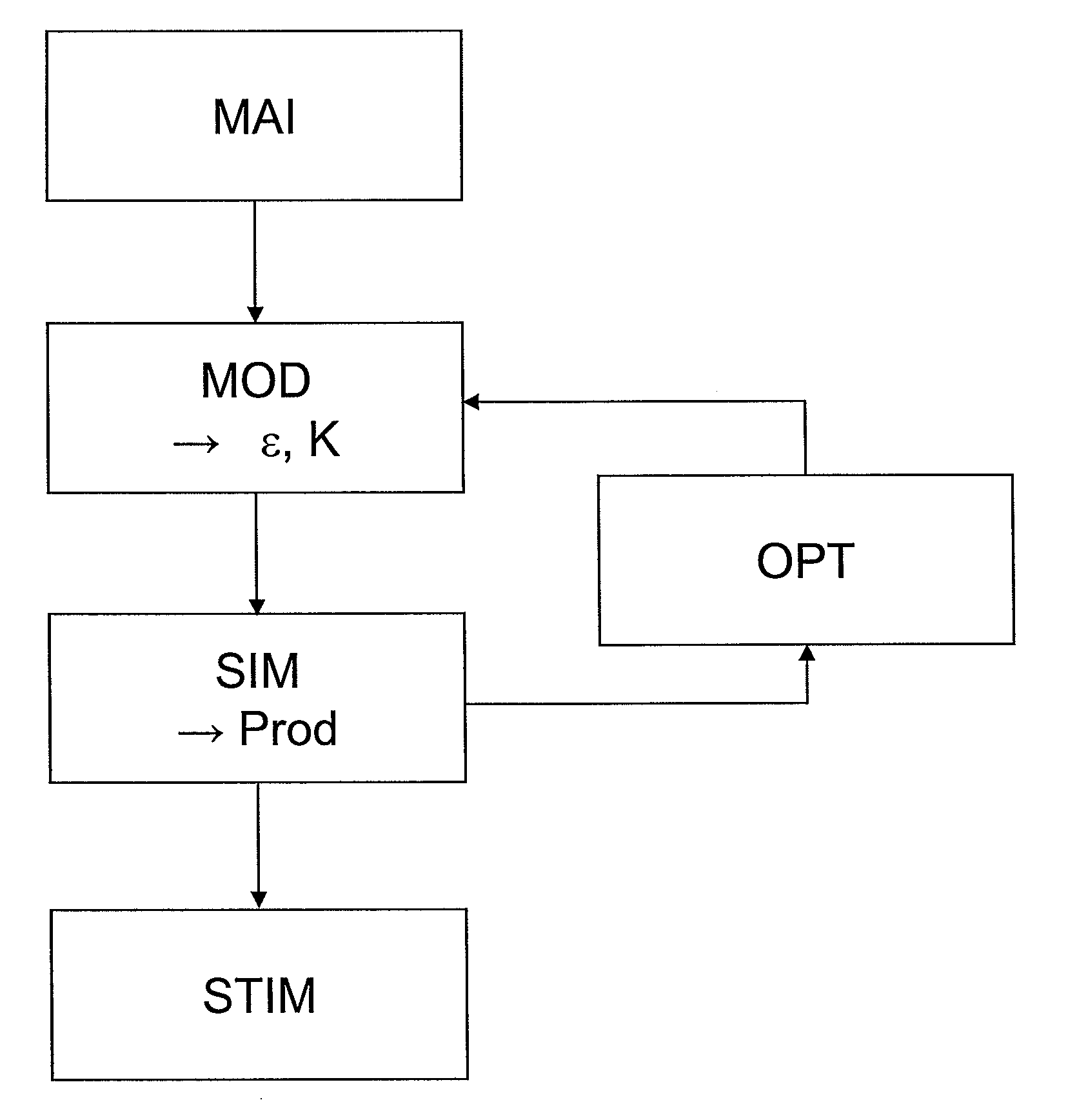
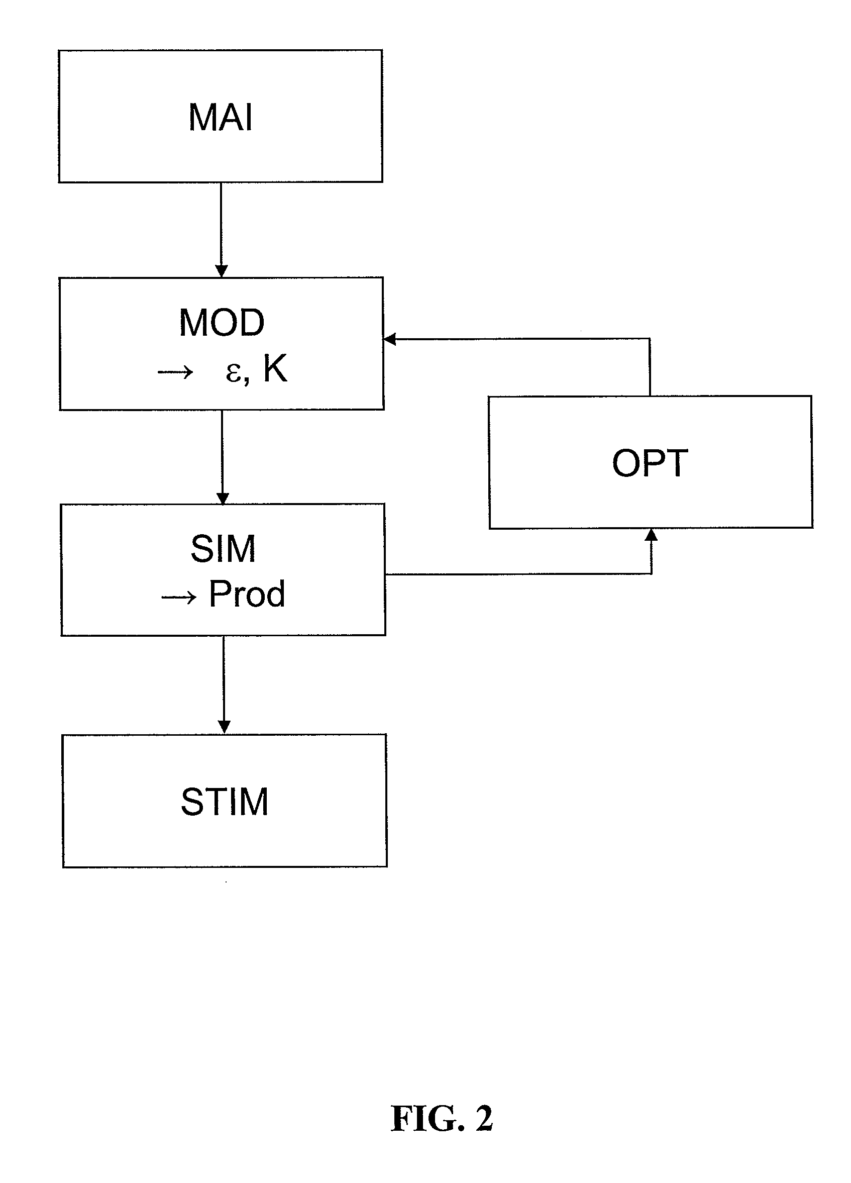
[0160] According to an example of application of the method according to the invention, we carry out a well-scale simulation of a constant-flow acid injection on a rock sample that is 2 m long, 40 cm wide and 40 cm high.

[0161] Gridding and Initialization:

[0162] After gridding the sample by means of a Cartesian grid (in this case, the grid is Cartesian and not radial as in the case of a well for example), the input data of the model are determined or defined:

[0163] Initial injection velocity V0=1.0−4 m / s [0164] Initial concentration C0=210 Kg / m3 [0165] Initial porosity ε0=0.36 [0166] Initial permeability K0=2.318.10−12 m2 [0167] Kinematic viscosity μ=1.10−3 Pa / s [0168] Rock density ρσ=2160 Kg / m3 [0169] Permeability in the dissolved medium Kf=8,331.10−8 m2 [0170] Mass stoichiometric coefficient v=1 [0171] Characteristic length of the problem L=0.1 m.

[0172] Experimental Determination of the Parameters

[0173] Reference results are determined by means of core-scale simulations using ...


PUM


Abstract

Method for modeling acidification within a porous medium as a result of the injection of an acid. A dual-medium model is constructed, considering a first sub-medium favourable to dissolution breakthroughs and a second sub-medium not favourable to dissolution breakthroughs. For each one of these sub-media, a metric-scale description of the acid transport, of the sub-medium and acid mass conservation and of the acid transfer from one sub-medium to the other sub-medium is achieved. This dual-medium model is then initialized from experimental calibrations. Finally, acidification of the medium is modelled by means of this dual-medium model.

Description

FIELD OF THE INVENTION [0001] The present invention relates to a method for modelling the acidification within a porous medium as the result of the injection of a chemical such as an acid. [0002] In particular, the invention allows to optimize acid injection parameters such as the flow rate and the zones to be treated within the scope of acid well stimulation in a carbonate context. [0003] In the petroleum industry, the production of a well can be greatly reduced as a result of damage in the neighbourhood of the well. Damage comes in form of an alteration of the permeability and of the nature of the rock around the well. There are many operations likely to damage the well: drilling, casing, cementing, development, completion and treatment. The consequence of such damage is formation clogging, and thus hydrocarbon production reduction or even stop. It is therefore very important for the petroleum industry to identify, on the one hand, the damage type and, on the other hand, the damag...

Claims


Application Information

Patent Timeline
18 Oct 2007
Publication
US20070244681A1
IPC
G06G7/48
CPC
E21B43/25
Inventors
COHEN, CHARLES EDOUARD; DING, DIDIER