
Trip lever assembly

a technology of lever assembly and trip lever, which is applied in the direction of water installation, flushing device, construction, etc., can solve the problems of low-budget or poorly constructed fixtures, user noise, rattle and other noises, etc., and achieves smooth rotational motion, less play, and improved feel

Active Publication Date: 2007-10-25
KOHLER CO
View PDF15 Cites 0 Cited by
  • Summary
  • Abstract
  • Description
  • Claims
  • Application Information

AI Technical Summary

Benefits of technology

[0007]The invention provides a trip lever assembly designed to provide an improved feel with less play and smoother rotational motion. The assembly has a stemmed handle supporting two bushings. Close tolerances and a positive mechanical connection are achieved between the inner bushing and the handle to limit play between these components. A high viscosity dampening material can be applied between the inner and outer bushings to further reduce play, particularly in the lateral direction, as well as smooth out the rotation of the handle and return the handle to its initial, resting position in a slow, smooth stroke.
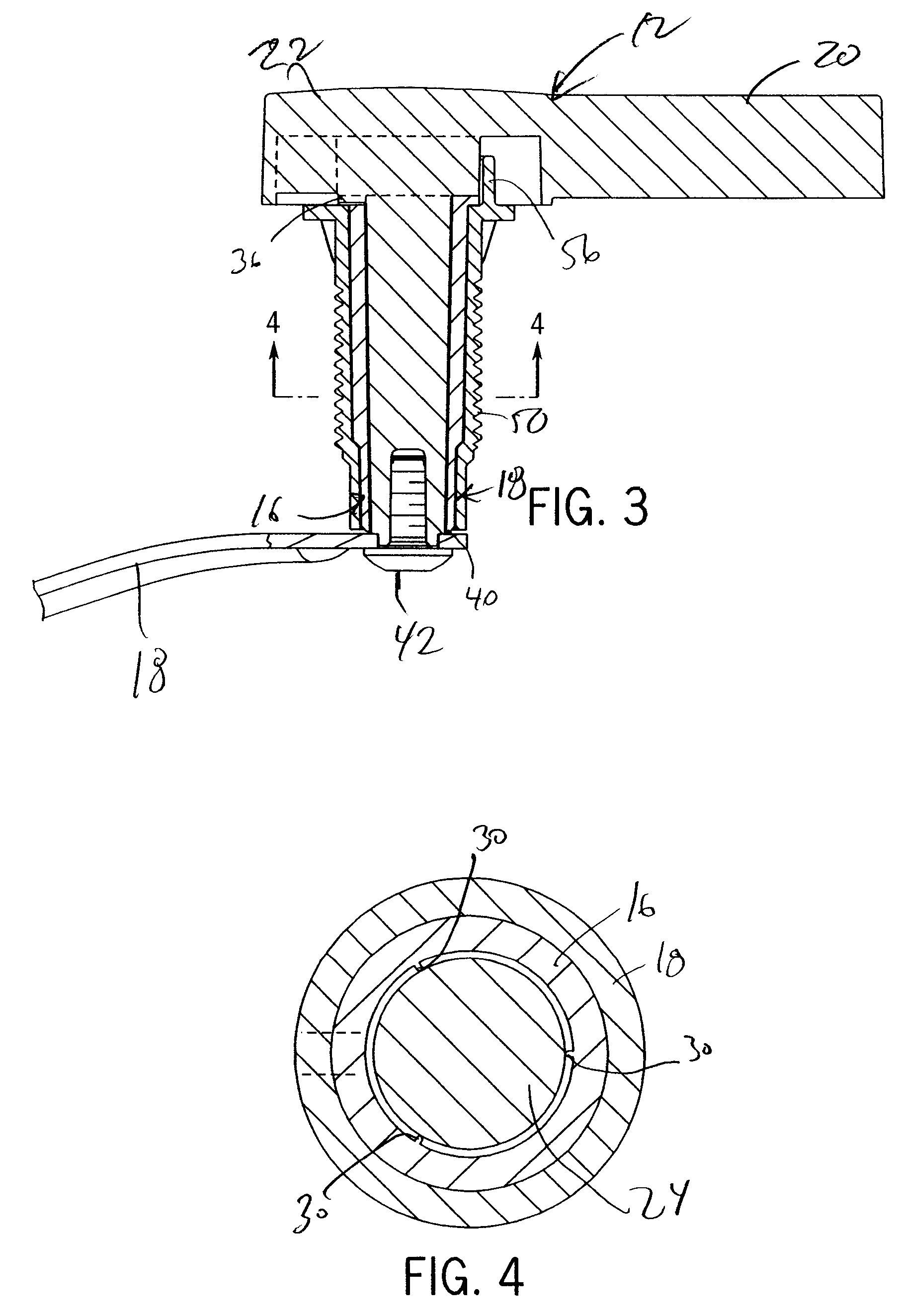
[0010]In addition to the positive mechanical connection between the inner bushing and the handle, other features of the trip lever assembly help to achieve a high integrity handle with a solid connection and smooth rotational motion. For instance, handle can be a metal (and thus more weighty) while low cost, plastics can be used for the bushings. The distal end of the stem can have an anti-rotation feature that is matable with the trip arm to prevent relative rotation therebetween. Also, the inner bushing can have one or more crushable ribs at an interior surface that deform as the stem is inserted into the inner bushing, thereby taking up any gap from manufacturing tolerances that would otherwise give the assembly a loose connection. Further, a dampening material, such as a high viscosity greased, can be disposed between the inner and outer bushings. This will further reduce play in the lateral direction perpendicular to the pivot axis. More importantly, it will smooth the rotational motion of the handle and work to slow the return of the handle to its initial position, thereby giving the handle a high integrity appearance, as if controlled or mounted by a more complex rotational system, such as a bearing or other such component.
[0011]In another aspect the trip lever assembly has a handle accessible from an exterior of the toilet and a stem extending into an interior of the toilet along a pivot axis. The handle rotates a trip arm and has a first anti-rotation feature that engages with a second anti-rotation feature of an inner bushing mounted about the stem to cause the inner bushing to rotate with the handle. An outer bushing is mounted about the inner bushing in a fixed position (as when mounted to a fixed object inside the toilet) to allow for relative rotation between the inner and outer bushings. A dampening material, such as a high viscosity dampening grease, is disposed between the inner bushing and the outer bushing.

Problems solved by technology

One problem with conventional trip lever assemblies is that they are often manufactured with very loose tolerances and thus provide a sloppy feel and appearance to the user, and they can also rattle and make other noises, especially when the handle is rotated back to its initial position.
These problems can give the user an impression that the fixture is low-budget or poorly constructed.

Method used


Image

  • Trip lever assembly
  • Trip lever assembly
  • Trip lever assembly

Examples


Embodiment Construction

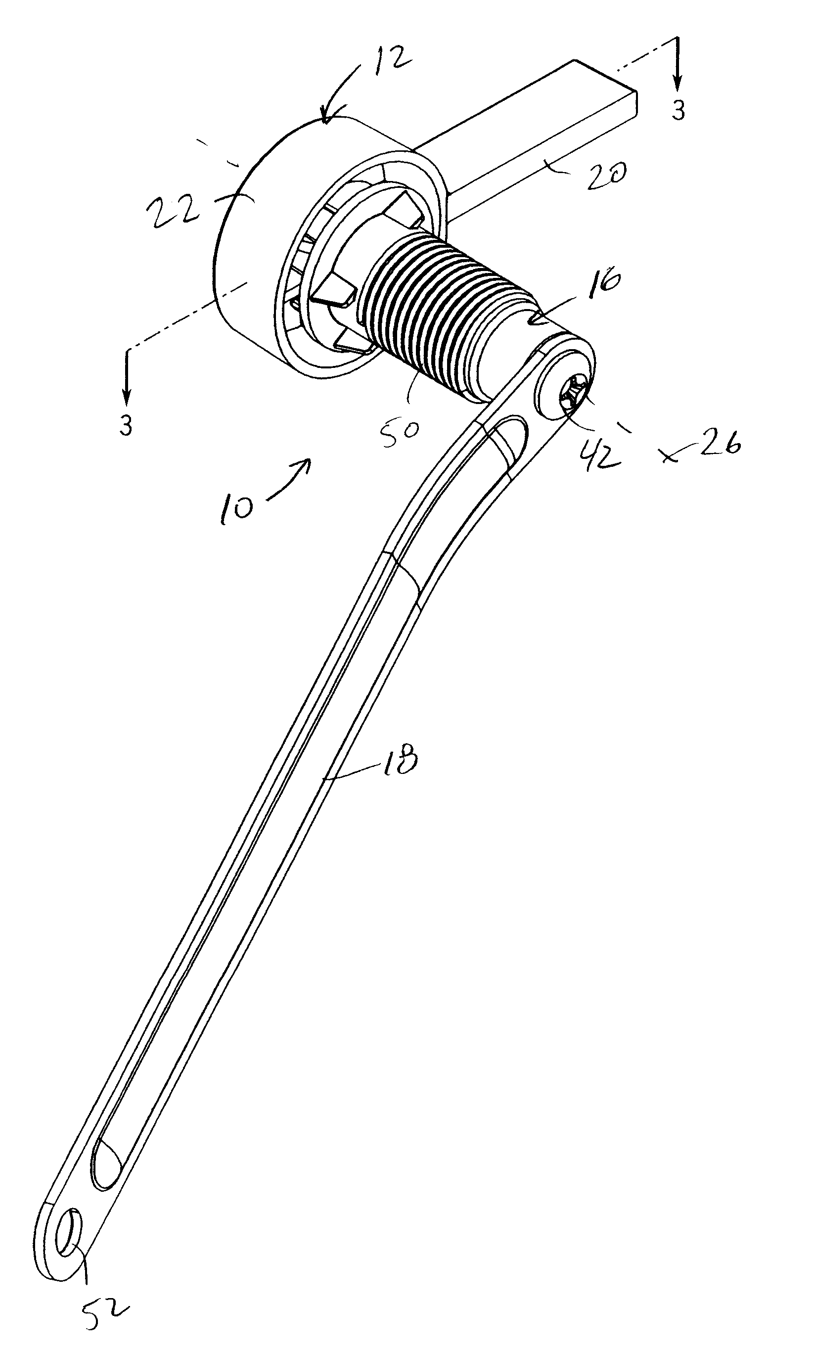
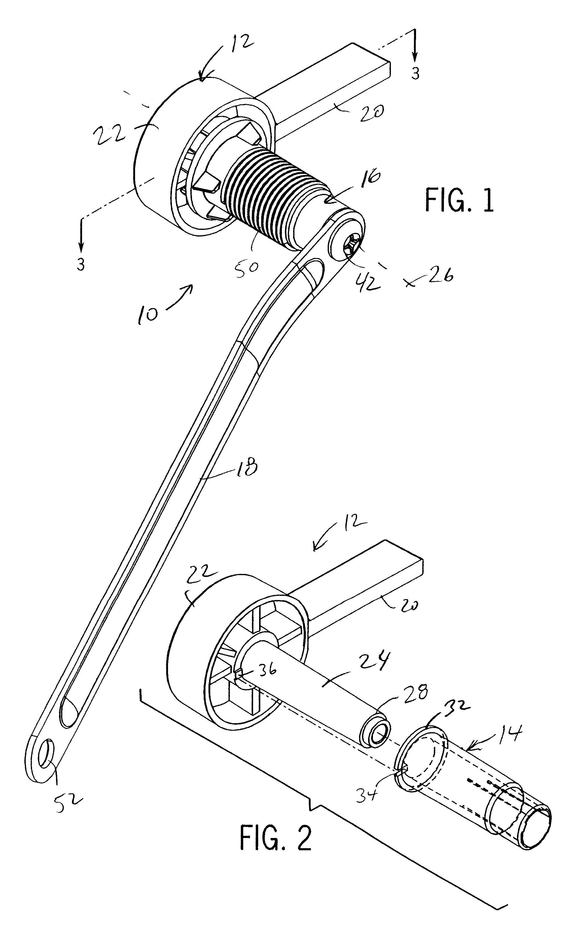
[0017]FIG. 1 illustrates an exemplary trip lever assembly 10 of the present invention for initiating the flush cycle of a toilet (not shown). The trip lever assembly 10 can be used by the user to operate the flush valve of a conventional toilet, for example, by being linked to the pull cord or chain (not shown) connected to the movable part of the flush valve, such as a flapper member (not shown), to unseat the movable part and commence a flow of water from the tank into the bowl of the toilet. As described below, in addition to providing the basic operational functions, the trip lever assembly 10 has several features that make it a high integrity assembly with a more solid feel with less play and smooth rotational motion.

[0018]Referring to FIGS. 1-3, the trip lever assembly 10 includes a handle 12, an inner bushing 14 (see FIG. 2), an outer bushing 16 and a trip arm 18. The handle 12 is preferably a finished and polished metal or other such material with high aesthetic value and so...


PUM


Abstract

A trip lever assembly for initiating a flush cycle of a toilet is constructed to have a more solid and smooth feel with less play. The assembly includes a handle accessible with a stem extending into an interior of the toilet. An inner bushing fits onto the stem and inside of a fixed outer bushing. A trip arm connect the handle to a pull member operatively attached to the flush valve. The handle has an anti-rotation feature that engages an associated feature of the inner bushing so that the inner bushing mechanically couples and rotates with the handle. A high viscosity dampening grease is disposed between the inner bushing and the outer bushing to limit lateral play, and smooth the rotation of the handle.

Description

CROSS-REFERENCE TO RELATED APPLICATION[0001]This application claims priority to U.S. provisional patent application Ser. No. 60 / 793,559, filed on Apr. 20, 2006, and entitled “Trip Lever Assembly”.STATEMENT OF FEDERALLY SPONSORED RESEARCH OR DEVELOPMENT[0002]Not applicable.BACKGROUND OF THE INVENTION[0003]The present invention relates to toilet trip lever assemblies.[0004]Plumbing fixtures such as toilets for cleaning and eliminating waste are well known. The flush cycle of toilet is initiated by a user depressing the handle of the trip lever at the outside of the toilet tank. This causes a trip arm inside of the tank to raise a pull chain which pulls the movable member of a flush valve (such as a flapper member) upward and unseat. When the valve is unseat, water from the tank is permitted to rush into the bowl and cause it to flush the waste and water therein into the waste plumbing lines of the building.[0005]One problem with conventional trip lever assemblies is that they are ofte...

Claims


Application Information

Patent Timeline
IPC IPC(8): E03D5/00
CPCE03D5/092
Inventor DUTTON, ERICZIMBRIC, LUKE
Owner KOHLER CO
Learn More