Eureka AIR delivers breakthrough ideas for toughest innovation challenges, trusted by R&D personnel around the world.

Weather strip

Inactive Publication Date: 2007-10-25
TOYODA GOSEI CO LTD
View PDF18 Cites 20 Cited by
  • Summary
  • Abstract
  • Description
  • Claims
  • Application Information

AI Technical Summary

Benefits of technology

[0023] In view of these situations, an object of the invention is to provide a weather strip which can ensure the prevention of intrusion of noise from a flange formed along a body opening portion into a passenger compartment of a vehicle even though the weather strip is mounted in a corner portion.
[0024] Another object of the invention is to provided a weather strip which can ease mounting work by controlling longitudinal stretch and contraction thereof and prevent the intrusion of noise from a flange reliably even though it is mounted in an corner portion.

Problems solved by technology

However, the weight of the opening trim weather strip is increased because it has the metal insert, and force is necessary to fit the mounting base portion 120 on the flange 7 such that the flange 7 is inserted into the mounting base portion 120, whereby some labor hours are necessary to obtain a proper mounting, resulting in poor workability.
Consequently, to deal with these drawbacks, the hardness and shape of the holding lips formed in the interior of the mounting base portion 120 have been devised variously, but no sufficiently acceptable results have ever been provided.

Method used


Image

  • Weather strip
  • Weather strip
  • Weather strip

Examples


first embodiment

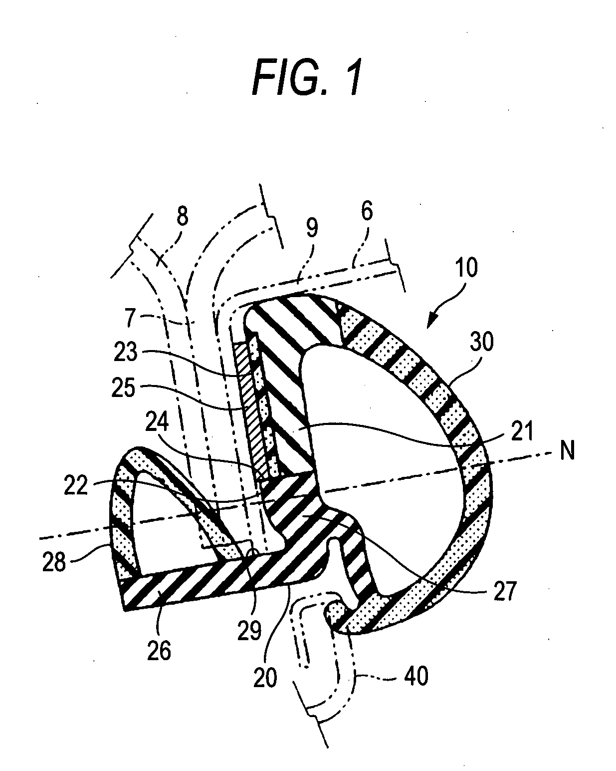
[0078]FIG. 1 is a sectional view of an opening trim weather strip 10 of the invention taken along the line I-I in FIG. 5 in such a state that the opening trim weather strip 10 is mounted on a body opening portion 6 shown in FIG. 4.

second embodiment

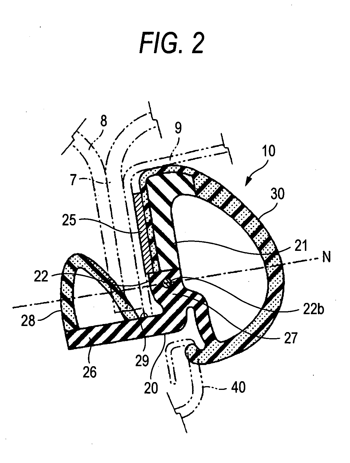
[0079]FIG. 2 is a sectional view of an opening trim weather strip 10 of the invention taken along the line I-I in FIG. 5 in such a state that the opening trim weather strip 10 is similarly mounted on the body opening portion 6 shown in FIG. 4.

third embodiment

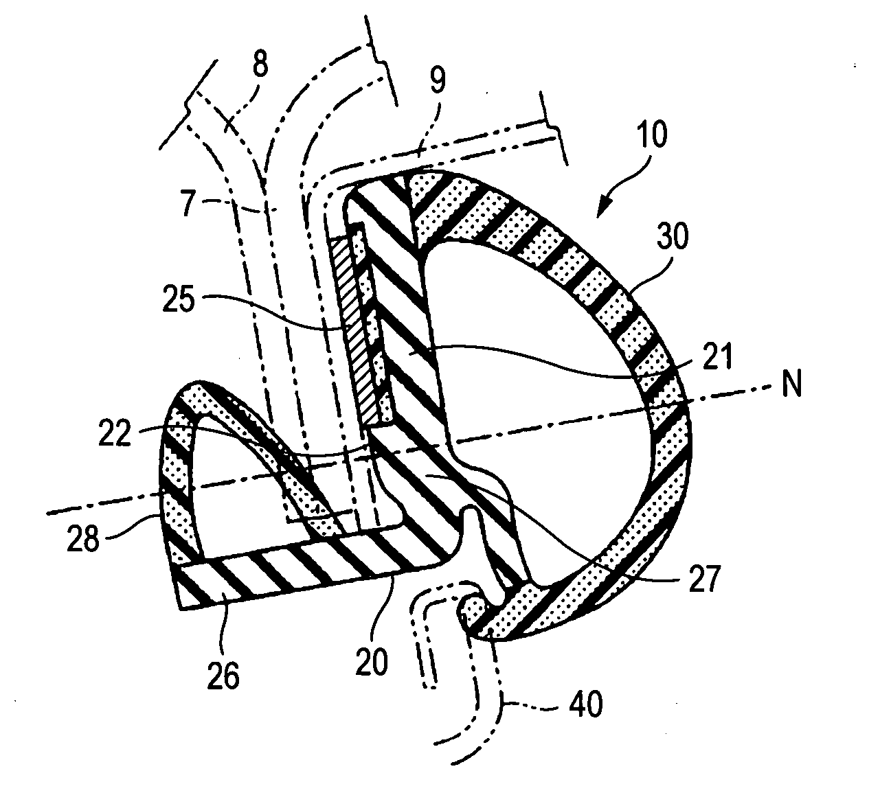
[0080]FIG. 3 is a sectional view of an opening trim weather strip 10 of the invention taken along the line I-I in FIG. 5 in such a state that the opening trim weather strip 10 is similarly mounted on the body opening portion 6 shown in FIG. 4.

[0081]FIG. 4 is a perspective view showing a state in which the opening trim weather strip 10 is mounted on the body opening portion 6 in such a state that a door of an automobile is left opened. FIG. 5 is a front view of the whole of the opening trim weather strip 10 which is to be mounted on the body opening portion 6.

[0082] As is shown in FIG. 4, a body 1 of the automobile has a body opening, and the body opening is covered and uncovered by a door 2 which is an open / close member. A periphery of the body opening coincides with the body opening portion 6, and distal edges of an outer panel 9, an inner panel 8 and the like, which make up the body 1, are welded together to a distal edge of the body opening portion 6 to thereby constitute a flan...


PUM


Abstract

There is provided a weather strip in which a mounting base portion of the weather strip includes a portion formed into a substantially L-shape in cross section which has at least a bottom wall and an exterior side wall. A pressure sensitive adhesive double coated tape is securely affixed to an internal surface of the exterior side wall. A stretch and contraction prevention portion is formed on the exterior side wall in a position which lies more centrally in a width direction of the exterior side wall than a connecting portion where the exterior side wall and the bottom wall are connected together. When the mounting base portion is curved in the width direction, a neutral plane of the curve is made to reside within the stretch and contraction prevention portion.

Description

BACKGROUND OF THE INVENTION [0001] 1. Field of the Invention [0002] The present invention relates to a weather strip which forms a seal between an open / close member such as an automotive door, a trunk lid and a sliding roof which covers and uncovers a body opening and a body opening portion. [0003] 2. Related Art [0004] Hereinafter, the invention will be described by taking for example an opening trim weather strip 10 which forms a seal between a door 2 and a body opening portion 6 of an automobile. [0005] Conventionally, a seal between the door 2 and the body opening portion 6 of the automobile is, as is shown in FIG. 8, accomplished by a door weather strip 160 which is mounted on an outer peripheral retainer 4 of a door frame of the door 2, a glass run 150 which is mounted in an inner peripheral channel 3 of the door frame, and an opening trim weather strip 110 which is mounted on a flange 7 of the body opening portion 6. [0006] Note that the flange 7 is provided with an outer pan...

Claims


Application Information

Patent Timeline
IPC IPC(8): E06B7/22
CPCB60J10/0074B60J10/042B60J10/081B60J10/0042B60J10/0005B60J10/0011B60J10/085B60J10/248B60J10/35B60J10/84B60J10/16B60J10/18B60J10/76B60J10/86
Inventor OBA, KISATONOZAKI, MASAHIRO
Owner TOYODA GOSEI CO LTD
Why Eureka
Eureka Blog
Learn More