
Optimized configuration of a reverse flow combustion system for a gas turbine engine

a gas turbine engine and combustion system technology, applied in the combustion process, hot gas positive displacement engine plants, lighting and heating apparatus, etc., can solve the problems of bending, rather than straight, fuel injectors, and bent fuel injectors can be relatively more expensive and difficult to produce than straight-shafted fuel injectors

Inactive Publication Date: 2007-10-25
HONEYWELL INT INC
View PDF30 Cites 15 Cited by
  • Summary
  • Abstract
  • Description
  • Claims
  • Application Information

AI Technical Summary

Benefits of technology

The gas turbine engine described in this patent has a high pressure compressor, high pressure turbine, low pressure turbine, and a reverse flow combustor. The combustor has a combustor liner assembly, combustor dome, and a plurality of straight-shafted fuel injectors. The fuel injectors are coupled to the combustor dome and are operable to receive a flow of fuel and to supply it to the combustion chamber. The technical effect of this design is improved engine performance and efficiency through improved fuel mixing and reduced emissions.

Problems solved by technology

The technical problem addressed in this patent is the need for a turbofan engine with a single-stage high pressure turbine and a multi-stage low pressure turbine that includes straight-shafted fuel injectors, as this configuration is more cost-effective and easier to produce than the current bent fuel injector configuration.

Method used


Image

  • Optimized configuration of a reverse flow combustion system for a gas turbine engine
  • Optimized configuration of a reverse flow combustion system for a gas turbine engine
  • Optimized configuration of a reverse flow combustion system for a gas turbine engine

Examples


Embodiment Construction

[0011] The following detailed description of the invention is merely exemplary in nature and is not intended to limit the invention or the application and uses of the invention. Furthermore, there is no intention to be bound by any theory presented in the preceding background of the invention or the following detailed description of the invention.

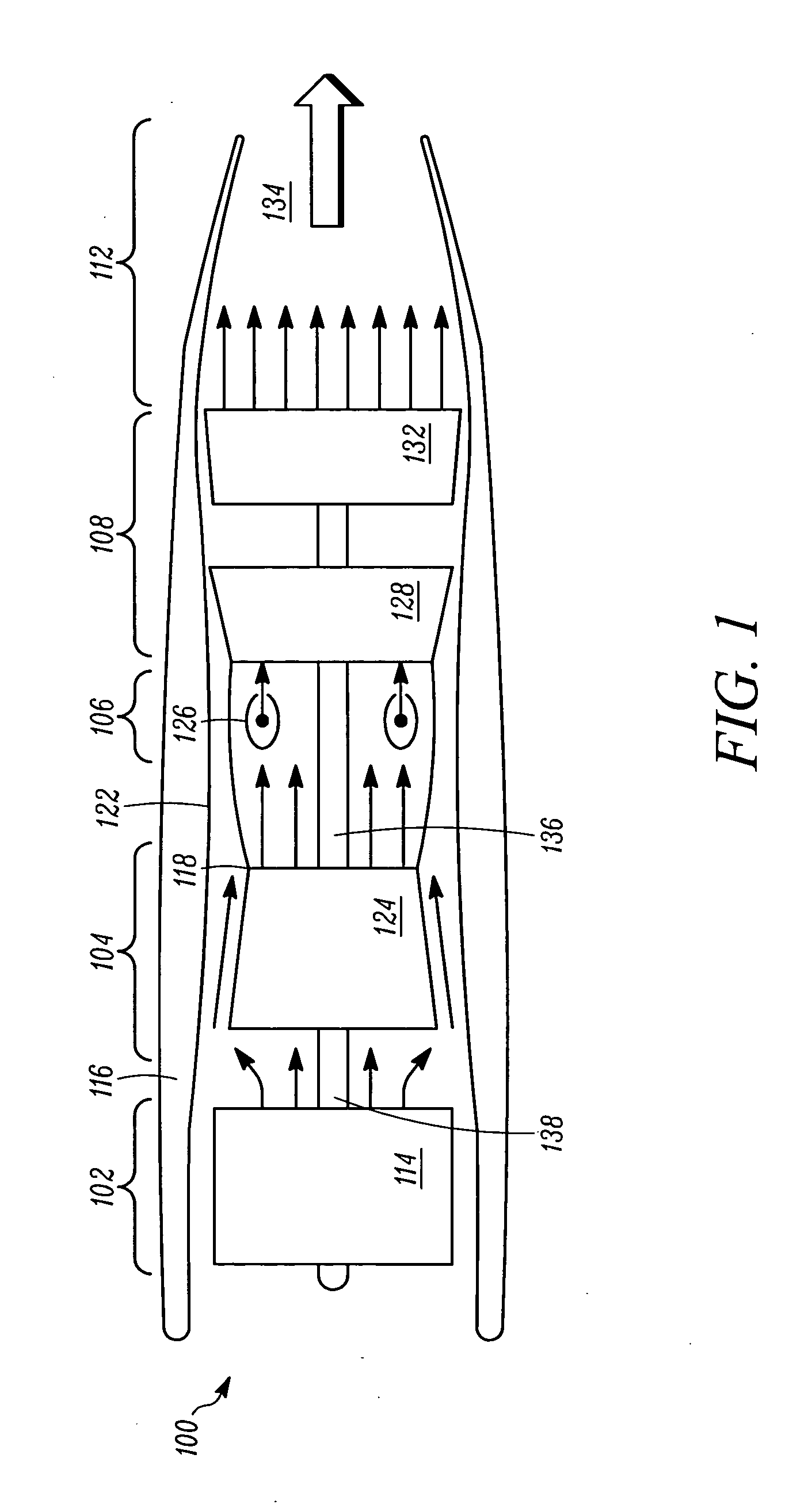
[0012]FIG. 1 depicts an embodiment of an exemplary multi-spool gas turbine main propulsion engine 100. The engine 100 includes an intake section 102, a compressor section 104, a combustion section 106, a turbine section 108, and an exhaust section 112. The intake section 102 includes a fan 114, which is mounted in a fan case 116. The fan 114 draws air into the intake section 102 and accelerates it. A fraction of the accelerated air exhausted from the fan 114 is directed through a bypass section 118 disposed between an engine cowl 122 and a compressor 124, and generates propulsion thrust. The remaining fraction of air exhausted from the fan...


PUM


Abstract

An apparatus is provided for a gas turbine engine. The gas turbine engine comprises a high pressure compressor, a single-stage high pressure turbine, a multi-stage low pressure turbine, and a reverse flow combustor unit. The reverse flow combustor comprises a combustor liner assembly, a combustor dome, and a plurality of straight-shafted fuel injectors. The combustor liner assembly includes an inner liner and an outer liner. The inner liner surrounds the single-stage high pressure turbine, and the outer liner is disposed radially outwardly of, and at least partially surrounding, the inner liner. The combustor dome assembly is coupled between the inner liner and the outer liner to define a combustion chamber therebetween. The plurality of straight-shafted fuel injectors are coupled to the combustor dome, with each fuel injector having at least an inlet, an outlet, and a linear fuel passageway extending therebetween.

Description


Claims


Application Information

Patent Timeline
Owner HONEYWELL INT INC
Features
  • Generate Ideas
  • Intellectual Property
  • Life Sciences
  • Materials
  • Tech Scout
  • Unparalleled Data Quality
  • Higher Quality Content
  • 60% Fewer Hallucinations
Learn More