Eureka AIR delivers breakthrough ideas for toughest innovation challenges, trusted by R&D personnel around the world.

Recuperative combustion system

a combustion system and recuperative technology, applied in the direction of solid fuel combustion, combustion types, lighting and heating apparatus, etc., can solve the problems of unproven long-term subterranean cosub>2 /sub>storage on a scale of hundreds to thousands of years (required for carbon dioxide mineralization), and achieve the effect of reducing or eliminating the amount of oxygen

Inactive Publication Date: 2011-02-24
REILLY TIMOTHY J
View PDF7 Cites 75 Cited by
  • Summary
  • Abstract
  • Description
  • Claims
  • Application Information

AI Technical Summary

Benefits of technology

"The patent describes a method and system for oxy-fuel combustion, which involves using oxygen and recycled flue gas to produce heat. The heat is then captured and used to power a water splitter, which produces hydrogen gas and oxygen gas. The oxygen gas is then transferred back to the combustion chamber for use in the combustion process. This method and system are efficient and can reduce the amount of oxygen required from an air separator unit or external source. Additionally, the patent describes a reaction between the hydrogen gas produced by the water splitter and carbon dioxide from the combustion flue gas to form methanol and water. Overall, the patent provides a technical solution for utilizing oxy-fuel combustion in a more efficient and economical way."

Problems solved by technology

While carbon capture and sequestration results in a reduction in atmospheric inputs of carbon from industrial sources, it will require large-scale construction of a pipeline distribution and storage system, which will be extremely costly to build.
Additionally, the effectiveness of long-term subterranean CO2 storage on a scale of hundreds to thousands of years (required for carbon dioxide mineralization) is presently unproven.

Method used


Image

  • Recuperative combustion system
  • Recuperative combustion system
  • Recuperative combustion system

Examples


Embodiment Construction

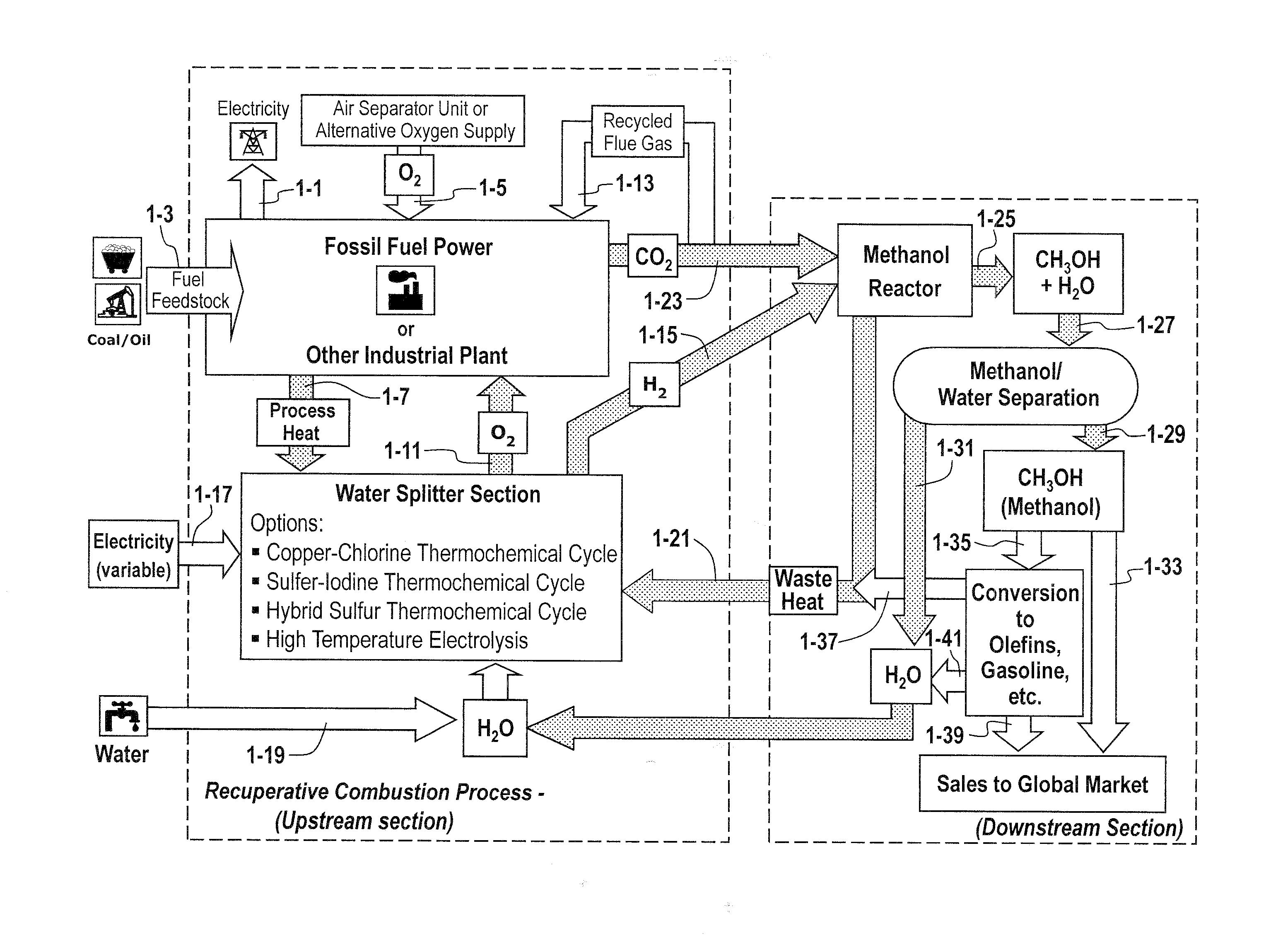
[0036]In one aspect, provided herein is a method for oxy-fuel combustion, comprising: providing a system comprising a combustion chamber arranged and disposed to receive fuel, oxygen and recycled flue gas and combust said fuel, oxygen and recycled flue gas to produce heat; capturing heat produced by the oxy-fuel combustion; using a portion of the heat to power a water splitter, thereby generating hydrogen gas and oxygen gas; and transferring the oxygen gas from the water splitter to the combustion chamber for use in said oxy-fuel combustion.

Combustion Chamber and Fuel

[0037]Oxy-fuel combustion for the production of electricity (FIG. 1-1) can occur in a variety of combustion systems. Non-limiting examples of combustion systems include: circulating fluidized bed boiler, pulverized coal boiler, and combustors. Combustible materials, including, but not limited to coal, coal / water slurry, petroleum products including oil, methane and natural gas, biomass, and plasma fuels (FIG. 1-3), may ...


PUM


Abstract

The methods and systems described herein relate to a recuperative combustion system that recuperates energy from fuel combustion that would otherwise be lost. The recuperative combustion system minimizes or eliminates the need for an air separator unit through the use of a clean water splitter section, consisting of a thermochemical cycle or high-temperature electrolysis. Water is split into its component hydrogen and oxygen, primarily with process heat from the combustion process. The oxygen produced by the water splitter provides oxygen necessary for oxy-fuel combustion, thereby reducing or eliminating the need for the power intensive air separator unit and / or external oxygen source, significantly increasing the efficiency of the oxy-fuel combustion cycle. Hydrogen produced by the water splitter may be used for a variety of industrial uses, or combined with carbon dioxide (captured from the flue gases produced by said combustion process) to produce methanol. Methanol can further be refined in a methanol to gasoline reactor to produce dimethyl ether, olefins or high grade gasoline. Described herein are methods and systems that 1) increase oxy-fuel combustion efficiency, 2) produce hydrogen for a suite of industrial / energy uses, and 3) capture carbon dioxide and convert it to high value hydrocarbons.

Description

RELATED APPLICATIONS [0001]This application claims priority to U.S. Provisional Application No. 61 / 274,745, filed Aug. 20, 2009, and U.S. Provisional Application No. 61 / 345,541, filed May 17, 2010. The entire contents of these patent applications are hereby incorporated herein by reference.FIELD OF THE INVENTION [0002]The methods and systems described herein relate to a recuperative combustion system that recuperates energy from fuel combustion that would otherwise be lost. The recuperative combustion system minimizes or eliminates the need for an air separator unit through the use of a clean water splitter section, consisting of a thermochemical cycle or high-temperature electrolysis. Water is split into its component hydrogen and oxygen, primarily with process heat from the combustion process. The oxygen produced by the water splitter provides oxygen necessary for oxy-fuel combustion, thereby reducing or eliminating the need for the power intensive air separator unit and / or extern...

Claims


Application Information

Patent Timeline
Patent Type & Authority Applications(United States)
IPC IPC(8): F23L7/00F23C9/00
CPCF23C9/00Y02E20/344Y02E20/14F23L7/007Y02E20/34
Inventor REILLY, TIMOTHY J.
Owner REILLY TIMOTHY J
Why Eureka
Eureka Blog
Learn More