Systems and methods for making foamed glass using submerged combustion

a technology of foamed glass and combustion melters, which is applied in the direction of glass rolling apparatus, glass tempering apparatus, manufacturing tools, etc., can solve the problems of insufficient high temperature properties, rapid melting of glass batches, offensive odors of glass products, etc., and achieve the effect of increasing density and decreasing density

Active Publication Date: 2013-04-11
JOHNS MANVILLE CORP
View PDF6 Cites 69 Cited by
  • Summary
  • Abstract
  • Description
  • Claims
  • Application Information

AI Technical Summary

Benefits of technology

[0020]a refractory or refractory-lined channel having an inlet and an outlet, the inlet configured to receive the initial foamy molten glass from the melter outlet and allows the initial foamy molten glass to traverse through the channel, the channel configured having a width and a depth for forming a zonal flow comprising a generally less dense upper flow of molten glass having generally decreasing density measured from the melter outlet to a downstream transport apparatus, and a generally denser lower flow of molten glass having generally increasing density measured from the melter outlet to a downstream dense glass processing apparatus, the densities compared to the density of the initial foamy glass,
[0021]the downstream transport apparatus configured to accept the foamy molten glass of generally decreasing density in it or on it to form a continuous ribbon of foamed molten glass having varying thickness and varying width, and
[0022]the downstream dense glass processing apparatus configured to accept the denser molten glass and form one or more dense glass products.

Problems solved by technology

However, these glass products may suffer from offensive odors and may not have adequate high temperature properties.
The introduction of high flow rates of oxidant and fuel into the molten glass, and the expansion of the gases cause rapid melting of the glass batch and much turbulence.
However, one drawback to submerged combustion is the tendency of the molten glass to foam.

Method used


Image

  • Systems and methods for making foamed glass using submerged combustion
  • Systems and methods for making foamed glass using submerged combustion
  • Systems and methods for making foamed glass using submerged combustion

Examples


embodiment 100

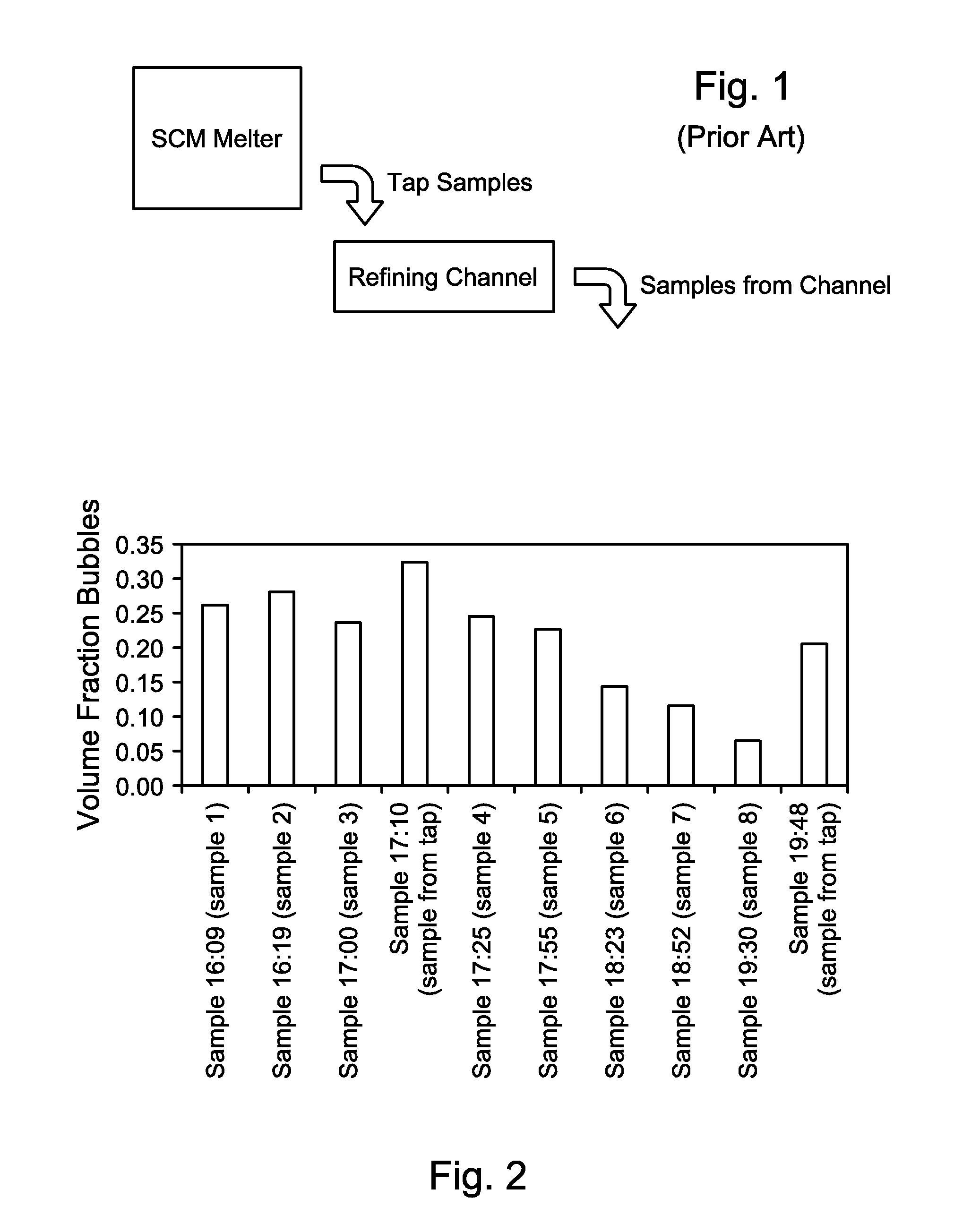
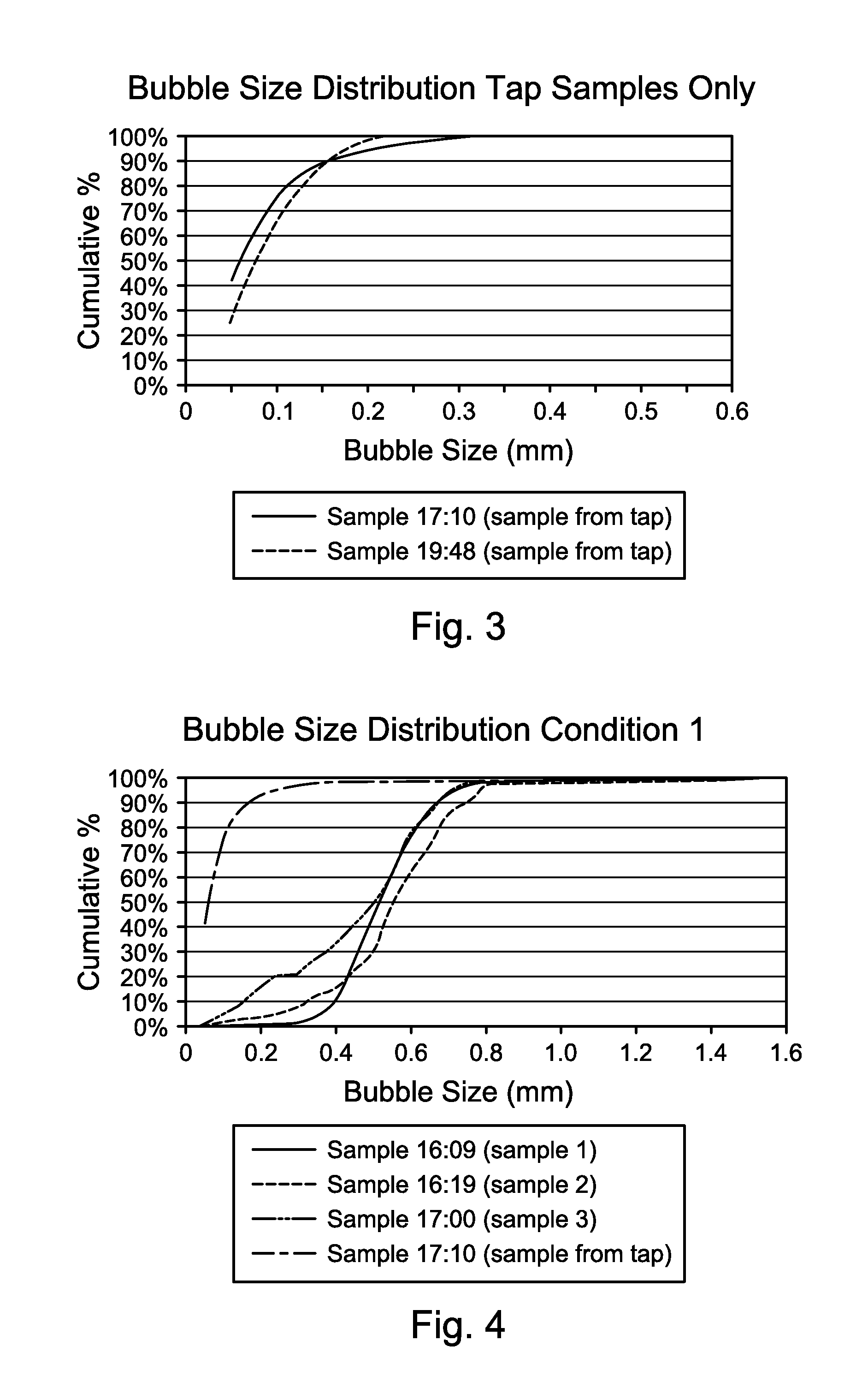
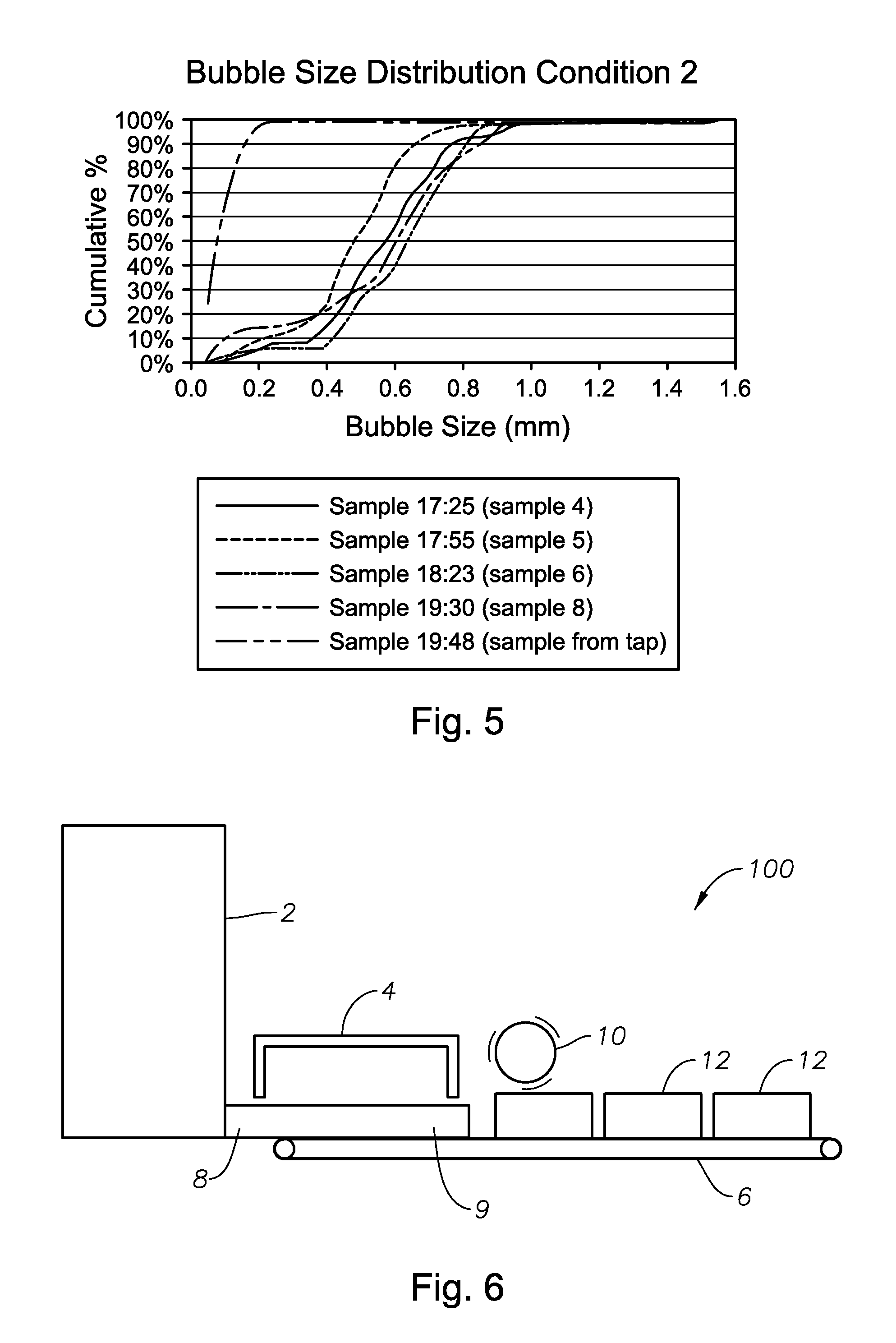
[0082]Specific non-limiting system and method embodiments in accordance with the present disclosure will now be presented in conjunction with FIGS. 6-12. The same numerals are used for the same or similar features in the various figures. In the views illustrated in FIGS. 6, 7 and 8, it will be understood in each case that the figures are schematic in nature, and certain conventional features are not illustrated in order to illustrate more clearly the key features of each embodiment. FIG. 6 illustrates a schematic side elevation view of a first system embodiment 100 comprising an SCM melter 2, an optional cooling and annealing lehr 4 downstream of melter 2, and a conveyor 6. An initial foamy molten glass 8 is discharged directly from the melter 2 to conveyor 6 in this embodiment. Initial foamy molten glass 8 discharged directly from melter 2 may be characterized as having small bubble diameters as measured and noted in Tables 1 and 2A and B and FIGS. 2-5. This initial foamy glass 8 w...

embodiment 400

[0094]FIGS. 9-12 are logic diagrams of four method embodiments of the present disclosure. FIG. 9 is a logic diagram of method embodiment 400, including the steps of melting glass-forming materials in a submerged combustion melter comprising an outlet, the melter producing an initial foamy molten glass having a density and comprising bubbles filled primarily with combustion product gases (box 402), depositing the initial foamy molten glass from the melter outlet directly onto or into a transport apparatus (box 404), and transporting the initial foamy molten glass to a processing apparatus using the transport apparatus (box 406).

embodiment 500

[0095]FIG. 10 is a logic diagram of method embodiment 500, which is a method of manufacturing foamed glass comprising the steps of melting glass-forming materials in a submerged combustion melter comprising an outlet, the melter producing an initial foamy molten glass having a density and comprising bubbles filled primarily with combustion product gases (box 502), depositing the initial foamy molten glass from the melter outlet directly onto or into a transport apparatus (box 504), and transporting the initial foamy molten glass to a processing apparatus using the transport apparatus, forming a continuous ribbon of molten foamed glass on or in the transport apparatus having varying thickness and varying width (box 506).


PUM

PropertyMeasurementUnit
diameteraaaaaaaaaa
diameteraaaaaaaaaa
thicknessaaaaaaaaaa

Abstract

Submerged combustion systems and methods of use to produce foamed glass. One system includes a submerged combustion melter having an outlet, the melter configured to produce an initial foamy molten glass having a density and comprising bubbles filled primarily with combustion product gases. The initial foamy molten glass is deposited directly onto or into a transport apparatus that transports the initial foamy molten glass to a downstream processing apparatus. An intermediate stage may be included between the melter and the transport apparatus. One intermediate stage is a channel that includes gas injectors. Another intermediate stage is a channel that produces an upper flow of a less dense glass and a relatively more dense glass lower flow. The upper flow may be processed into foamed glass products, while the more dense flow may be processed into dense glass products.

Description

CROSS-REFERENCE TO RELATED APPLICATIONS[0001]This application is related to assignee's U.S. non-provisional patent application Ser. No. 12 / 817,754, filed Jun. 17, 2010; Ser. No. 12 / 888,970, filed Sep. 23, 2010; Ser. No. ______, filed ______ (JM 8001); and Ser. No. ______, filed ______ (JM 8054), all of which are incorporated herein by reference.BACKGROUND INFORMATION[0002]1. Technical Field[0003]The present disclosure relates generally to the field of combustion furnaces and methods of use to produce glass, and more specifically to methods and apparatus for making foamed glass using submerged combustion melters.[0004]2. Background Art[0005]High temperature foamed glass production currently utilizes conventional glass melting technologies and knowledge of control of sulfur gas compounds solubility in molten glass to produce glass with a large volume fraction of bubbles to give the glass objects thermal insulating properties. However, these glass products may suffer from offensive odo...

Claims


Application Information

Patent Timeline
Patent Type & Authority Applications(United States)
IPC IPC(8): C03B19/08C03B35/00C03B25/00
CPCC03B19/08C03B5/2356C03B37/01C03B2211/22C03B2211/23Y02P40/50
Inventor SHOCK, JEFFREY M.HUBER, AARON MORGANSWALES, TIMOTHY G.
Owner JOHNS MANVILLE CORP
Why Eureka
Try Eureka