Pipe wrench stand

a technology of supporting stand and wrench, which is applied in the direction of wrenches, screwdrivers, manufacturing tools, etc., can solve the problems of sprained wrists, scalding skin, and affecting the use of the two wrenches in this manner,

Inactive Publication Date: 2007-10-25
SHIELDS ROBERT W
View PDF7 Cites 12 Cited by
  • Summary
  • Abstract
  • Description
  • Claims
  • Application Information

AI Technical Summary

Benefits of technology

[0008]Accordingly, the invention presents a pipe wrench having an effective built-in arm that allows the wrench to be self-supporting when utilized as a vise or the like. The invention provides for improved elements thereof in an arrangement for the purposes described that are inexpensive, dependable and fully effective in accomplishing their intended purposes.

Problems solved by technology

Employing two wrenches in this manner is somewhat difficult and hazardous in that the first wrench is held in one hand to prevent rotation while the second wrench must be pushed or pulled with the other hand to cause rotation.
In this scenario, slippage of one of the wrenches often results in injuries such as sprained wrists, broken hands and / or scraped skin.

Method used


Image

  • Pipe wrench stand
  • Pipe wrench stand
  • Pipe wrench stand

Examples


Embodiment Construction

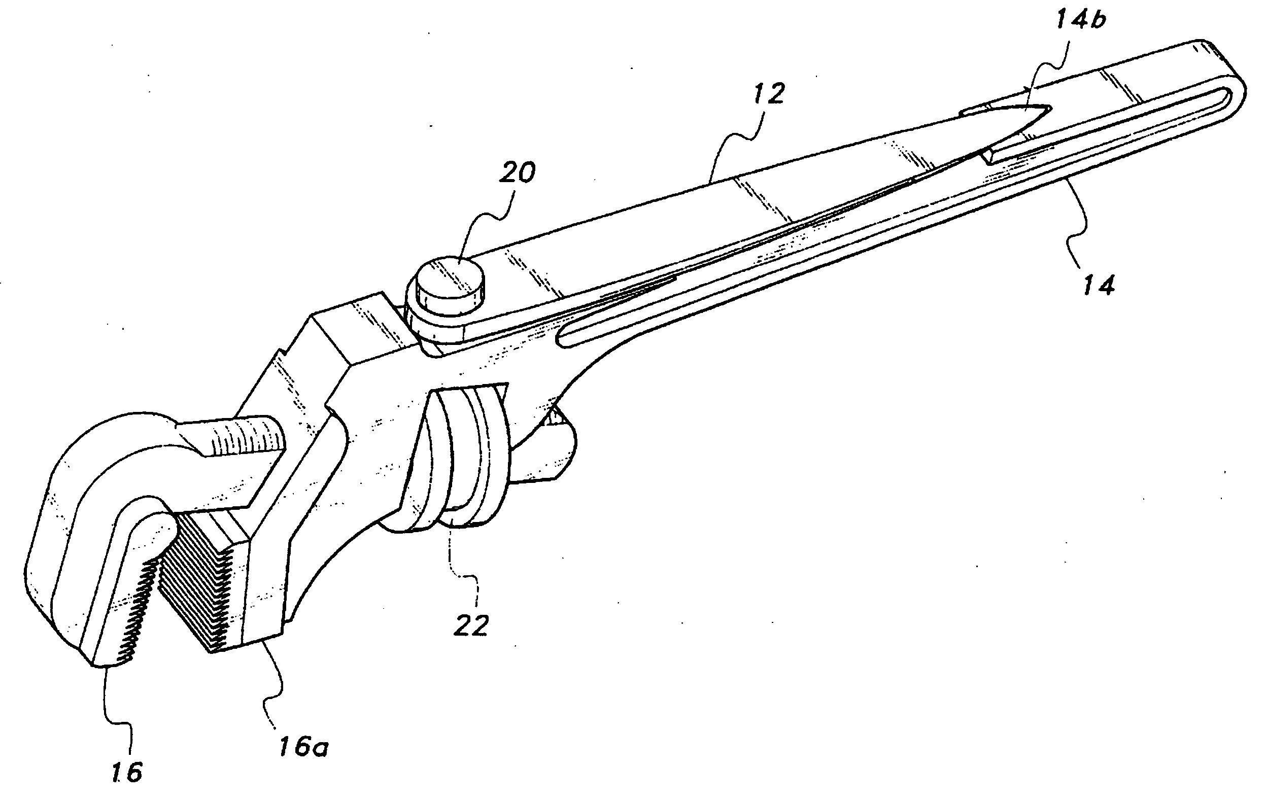
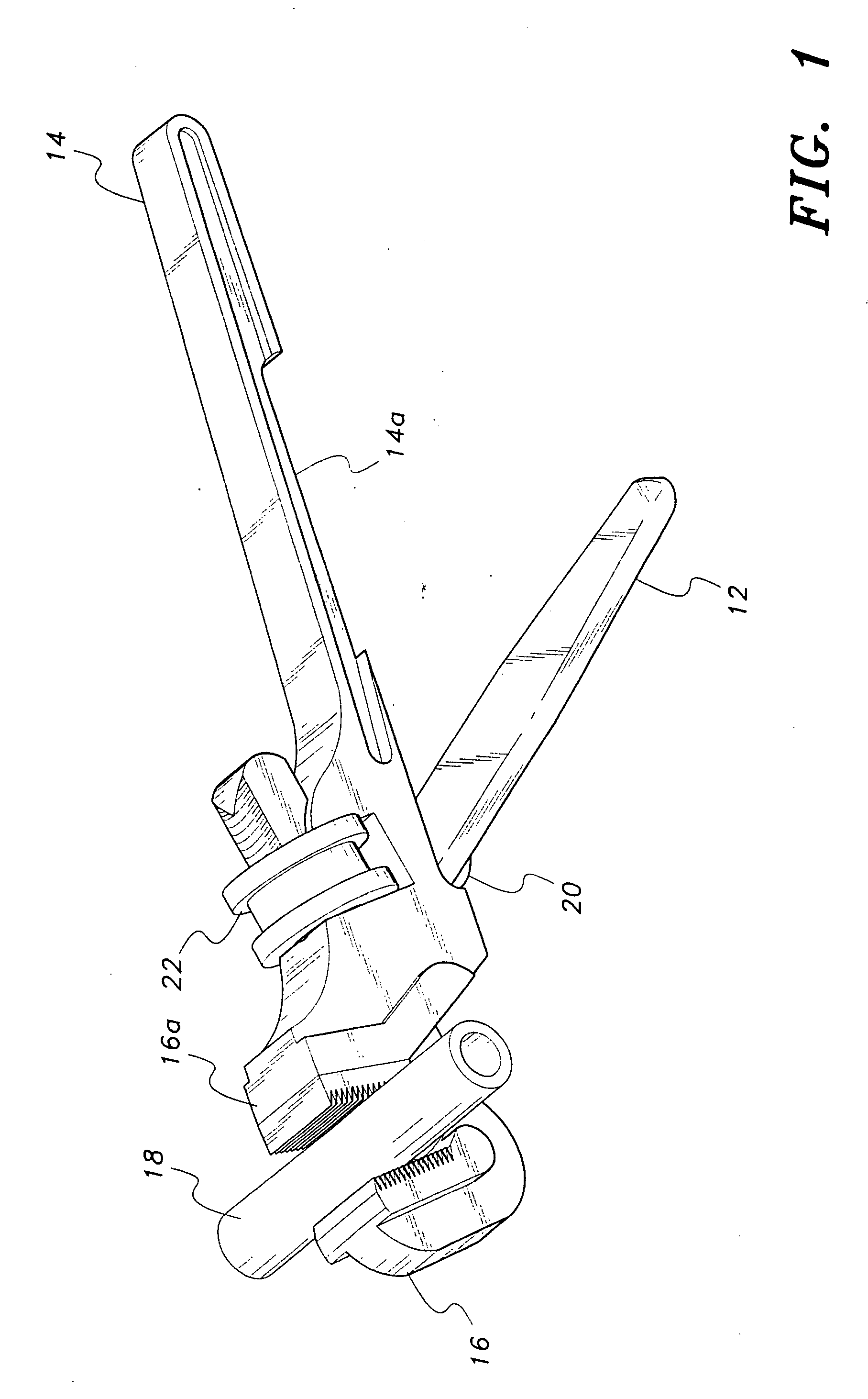
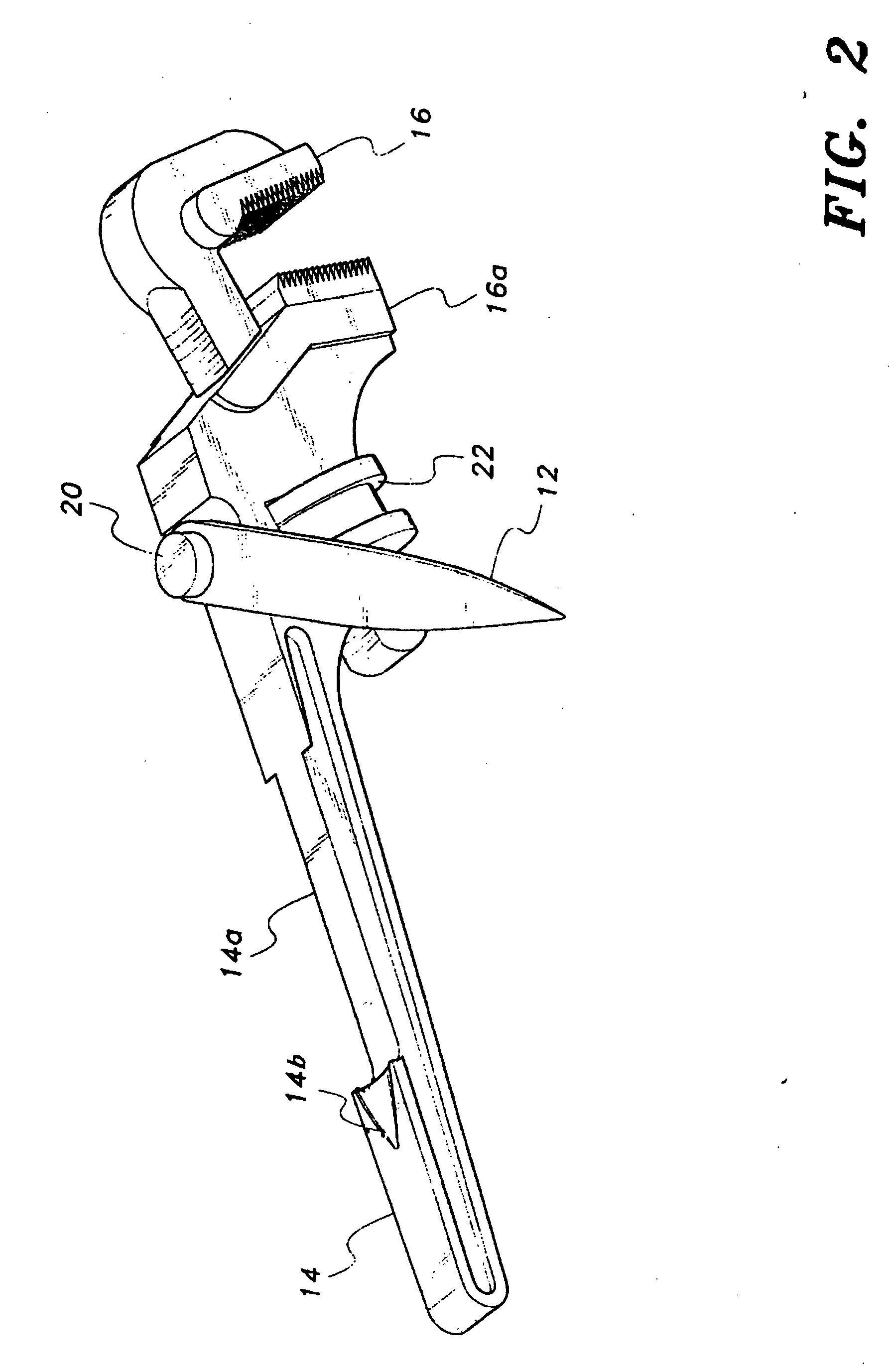
[0014]Attention is first directed to FIGS. 1 and 2 wherein the pipe wrench stand of the present invention is shown in an in-use position. The stand comprises an elongate arm 12 mounted on the rear surface of the handle 14 of a pipe wrench. The pipe wrench is provided with a head portion having conventional adjustable and stationery jaws 16, 16a for gripping a work piece such a pipe 18. Elongate arm 12 is mounted for pivoting movement on the rear surface of handle 14. A pivot pin 20 functions to provide the attachment means for mounting the arm to the handle. Pin 20 provides a permanent attachment in that the arm cannot be removed from the handle under normal use conditions. The pivot point defined by pin 20 is adjacent the adjustment knurl 22 located on the front surface of handle 14. When pivoted to positions as shown in the above-cited Figs., arm 12 provides means that permits the wrench to stand in an upright position on a planar surface and function as a vice or the like. The ar...


PUM


Abstract

A pipe wrench having a movable arm mounted thereon. The arm is pivotally attached to the back of the wrench and may be foldable for storage or pivoted to an in-use, support-stand position to allow the wrench to be self-supporting when desired.

Description

CROSS-REFERENCE TO RELATED APPLICATION[0001]This application claims the benefit of U.S. Provisional Patent Application Ser. No. 60 / 793,658, filed Apr. 21, 2006.BACKGROUND OF THE INVENTION[0002]1. Field of the Invention[0003]The present invention generally relates to hand tools. More specifically, the present invention is drawn to a pipe wrench having a pivoting support stand.[0004]2. Description of the Related Art[0005]The pipe wrench is probably the most frequently used tool in the plumbing art. In many instances, the plumbing job requires the use of two pipe wrenches wherein one of the wrenches is utilized as a vise and the second wrench is used to tighten or loosen the particular pipefitting. Employing two wrenches in this manner is somewhat difficult and hazardous in that the first wrench is held in one hand to prevent rotation while the second wrench must be pushed or pulled with the other hand to cause rotation. In this scenario, slippage of one of the wrenches often results i...

Claims


Application Information

Patent Timeline
Patent Type & Authority Applications(United States)
IPC IPC(8): B25B13/58B25B13/16
CPCB25G1/105B25B13/5058
Inventor SHIELDS, ROBERT W.
Owner SHIELDS ROBERT W
Why Eureka
Try Eureka