Electrical splice assembly

a technology of electrical splice assembly and assembly plate, which is applied in the direction of cable termination, contact member manufacturing, coupling device connection, etc., can solve the problems of high cost difficult to package such assembly in some vehicle areas, and complicated construction of current electrical splice assembly. , to achieve the effect of low cost and low profil

Active Publication Date: 2007-10-25
APTIV TECH LTD
View PDF4 Cites 20 Cited by
  • Summary
  • Abstract
  • Description
  • Claims
  • Application Information

AI Technical Summary

Benefits of technology

[0003] In one aspect, the invention provides a very low cost, low profile, single circuit electrical splice assembly that includes a bus plate having a plurality of coplanar, spaced male blades extending from the bus plate in cantilever fashion, a plurality of female terminals attached to the male blades, and a generally U-shaped housing of extrudable shape. The housing has ...

Problems solved by technology

Current electrical splice assemblies are complicated to build utilizing injection molded components, and a sub-assembly process before final assembly and testing.
Cur...

Method used


Image

  • Electrical splice assembly
  • Electrical splice assembly

Examples


Embodiment Construction

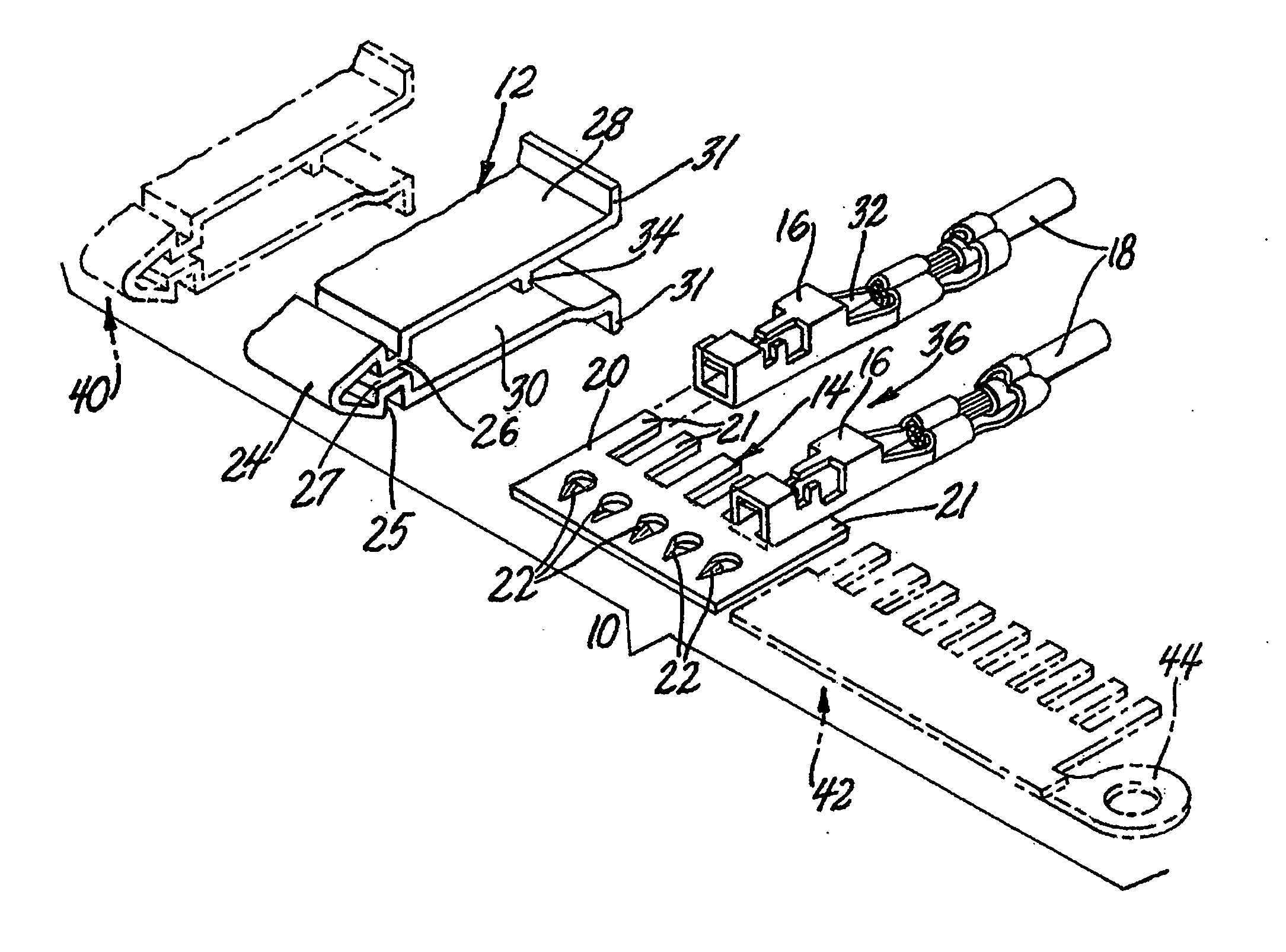
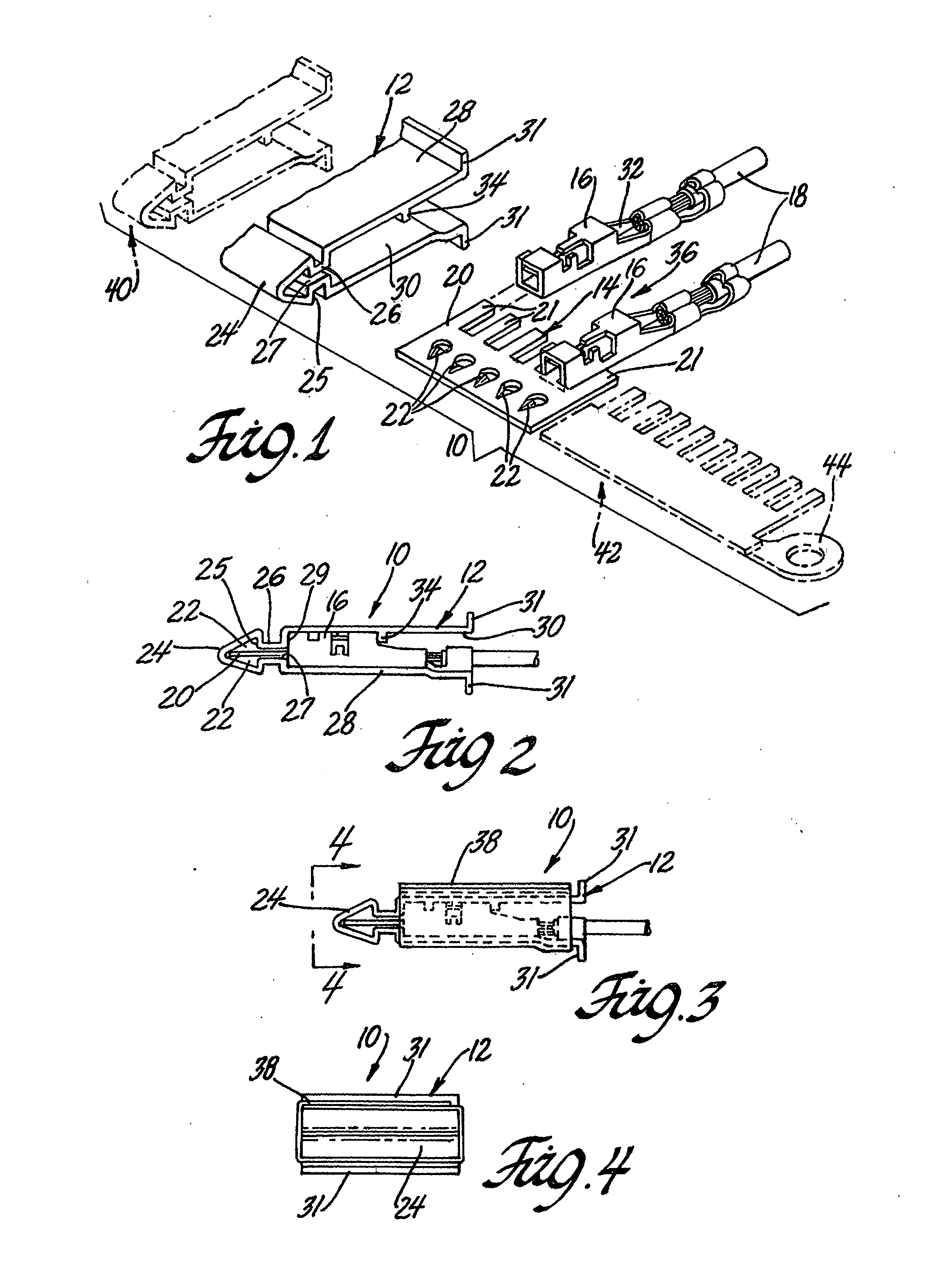
[0011] Referring now to the drawing, FIG. 1 is an exploded perspective view of an electrical splice assembly 10 of the invention. The electrical splice assembly 10 comprises an extrudable housing 12, a generally planar bus plate 14, and a plurality of female terminals 16 that are attached to the respective ends of insulated electric cables 18.

[0012] Bus plate 14 has a forward strap 20 and a plurality of coplanar, spaced male blades 21 that extend from a rearward end of the forward strap 20 in cantilever fashion. The forward strap 20 preferably includes a plurality of darts 22 that are laterally aligned and laterally spaced from each other. Some of the darts 22 project upwardly and some of the darts project downwardly with the preferred arrangement being that every other dart projects in the same direction as best shown in FIG. 1.

[0013] The extrudable housing 12 is a generally U-shaped housing of uniform cross section, having a triangular, forward closed end portion 24, an intermed...


PUM


Abstract

An electrical splice assembly includes a bus plate having a plurality of coplanar, spaced male blades extending from the bus plate in cantilever fashion, a plurality of female terminals attached to the male blades, and a generally U-shaped housing of extrudable shape. The housing has an elongate open end portion defining a terminal receiving cavity, a closed end portion and an intermediate portion defining a slot that communicates with the terminal receiving cavity. The bus plate is at least partially disposed in the slot and the spaced male blades are at least partially disposed in the terminal receiving cavity along with the female terminals attached to them. The bus plate is a sheet metal stamping and the housing is an extrusion. The female terminals are attached to selected ones of the male blades to form a sub-assembly that is inserted laterally into the housing so the bus plate is at least partially disposed in the slot and the female terminals are disposed in the terminal receiving cavity. During manufacture a bus plate of appropriate length may be severed from a long sheet metal bus plate precursor and a housing of appropriate length may be severed from a long extruded housing precursor.

Description

FIELD OF THE INVENTION [0001] This invention relates to an electrical splice assembly. BACKGROUND OF THE INVENTION [0002] Current electrical splice assemblies are complicated to build utilizing injection molded components, and a sub-assembly process before final assembly and testing. Current electrical splice assemblies are expensive, have many different configurations and are very large making it difficult to package such assemblies in some vehicle areas. SUMMARY OF THE INVENTION [0003] In one aspect, the invention provides a very low cost, low profile, single circuit electrical splice assembly that includes a bus plate having a plurality of coplanar, spaced male blades extending from the bus plate in cantilever fashion, a plurality of female terminals attached to the male blades, and a generally U-shaped housing of extrudable shape. The housing has an elongate open end portion defining a terminal receiving cavity, a closed end portion and an intermediate portion defining a slot th...

Claims


Application Information

Patent Timeline
IPC IPC(8): H01R9/05
CPCH01R4/185H01R13/113H01R43/18H01R31/08H01R43/16H01R13/422
Inventor PETERSON, DAVID R.DAUGHERTY, JAMES D.
Owner APTIV TECH LTD
Why Eureka
Try Eureka