Power Inverter

Active Publication Date: 2007-10-25
HITACHI ASTEMO LTD
View PDF8 Cites 43 Cited by
  • Summary
  • Abstract
  • Description
  • Claims
  • Application Information

AI Technical Summary

Benefits of technology

[0028]An effect of the present invention

Problems solved by technology

However, trend of on-board rotating electric machines is toward increasing power resulting in a larger heat release value than in

Method used


Image

  • Power Inverter
  • Power Inverter
  • Power Inverter

Examples


Embodiment Construction

[0045]The following explains embodiments of the power inverter by the present invention with reference to the accompanying drawings.

(Electric Vehicle 100)

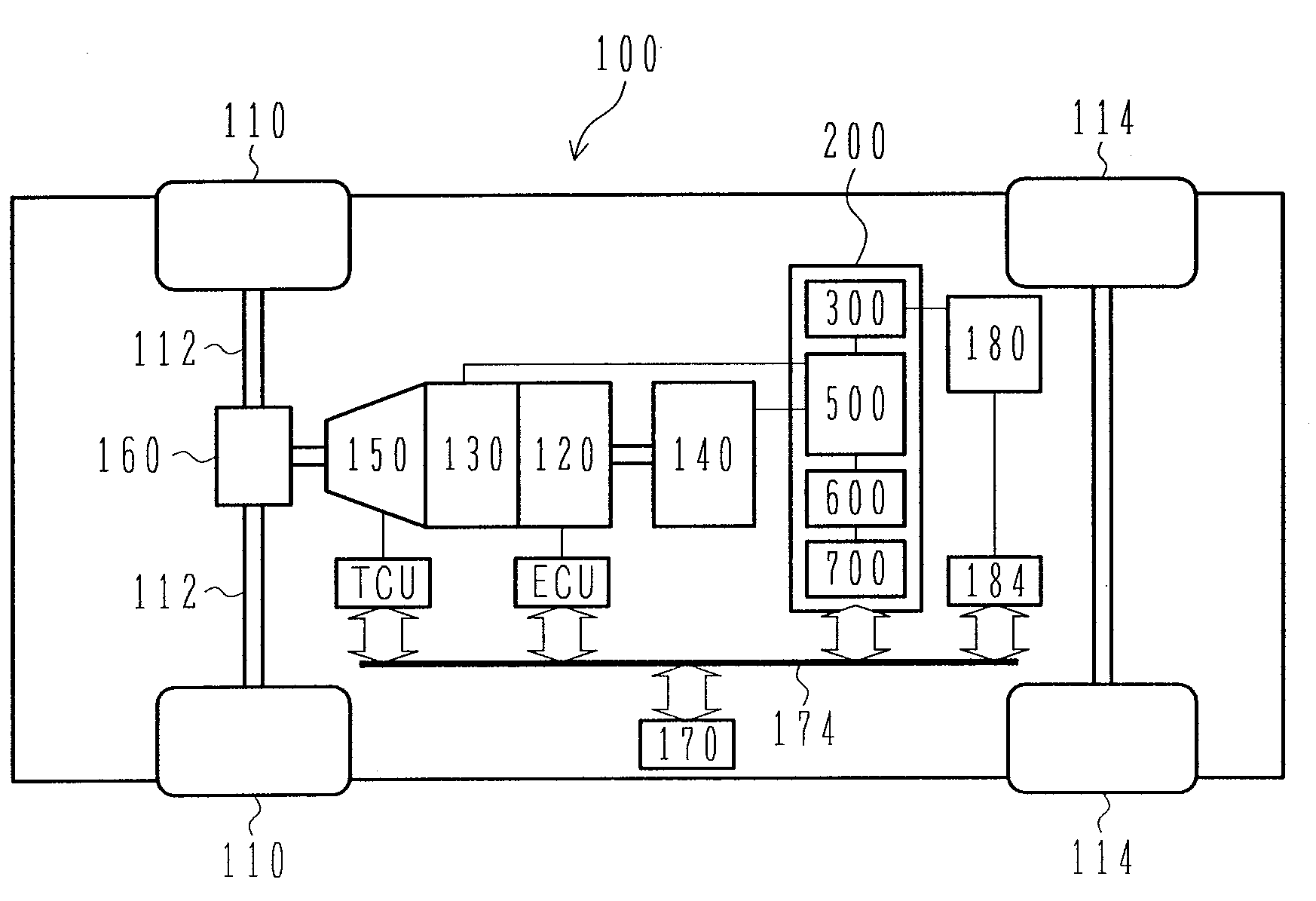
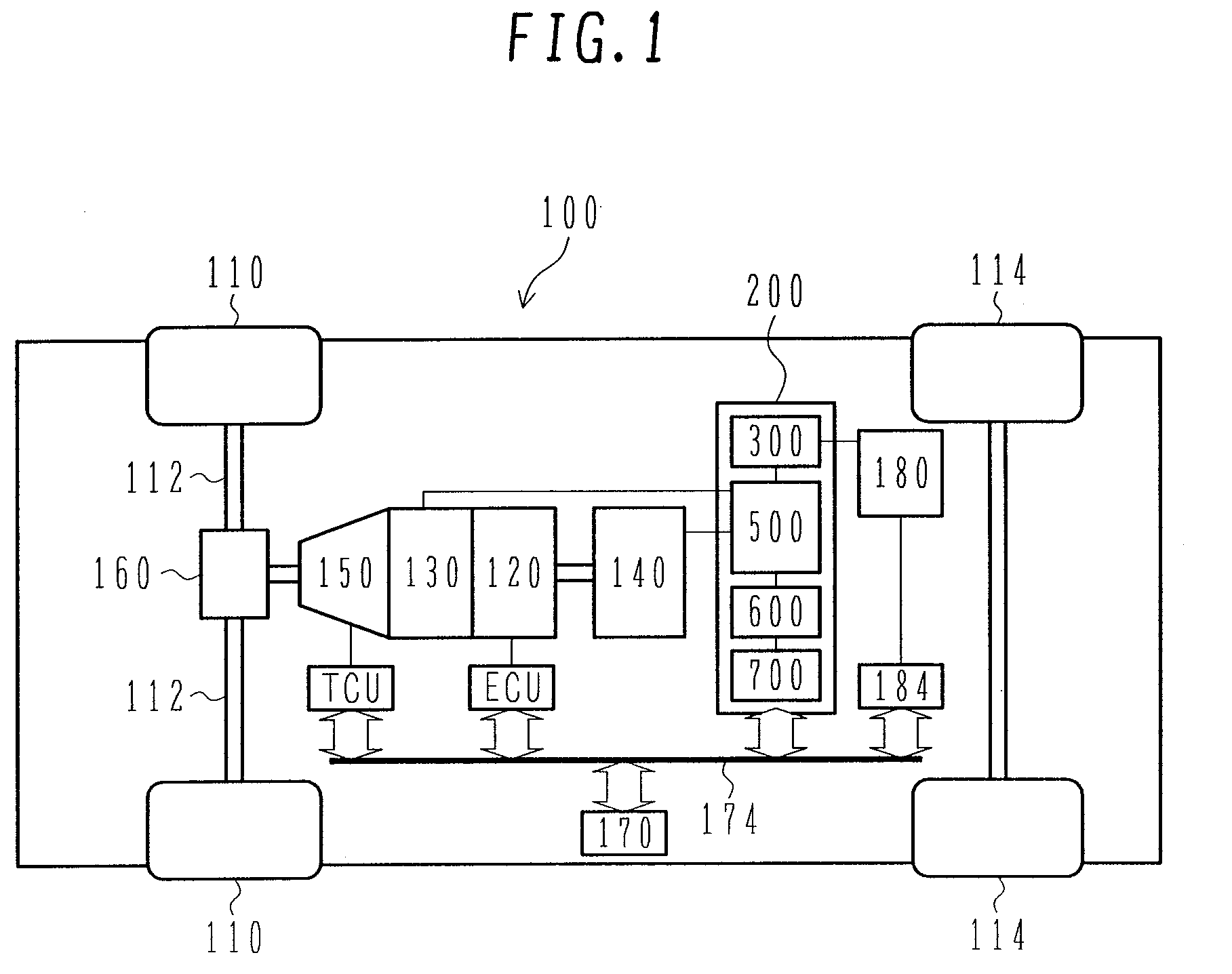
[0046]FIG. 1 is a schematic diagram showing a hybrid electric vehicle which can mount the power inverter according to an embodiment of the present invention. A power inverter 200 according to the present invention can obviously be applied also to a pure electric vehicle, and many of basic configurations and operations are common to a hybrid electric vehicle and a pure electric vehicle. Therefore, the following explains some embodiments of hybrid electric vehicle as a representative case.

[0047]A hybrid electric vehicle 100 having front wheels 110 and rear wheels 114 is provided with an engine 120, a first rotating electric machine 130, a second rotating electric machine 140, and a battery 180 which supplies high-voltage DC power to the first rotating electric machine 130 and second rotating electric machine 140. Actually, a battery ...


PUM


Abstract

A power inverter comprises at least a box-shaped housing; and a power module, a smoothing capacitor, a base plate made of a flat plate, and a rotating electric machine control circuit board arranged in order in the housing. The base plate is arranged with the fringes fixed to the inner wall surfaces of the housing, and the smoothing capacitor and rotating electric machine control circuit board are fixed.

Description

BACKGROUND OF THE INVENTION [0001]1. Field of the Invention[0002]The present invention relates to a power inverter, for example, a power inverter suitable for a vehicle.[0003]2. Description of the Related Art[0004]A power inverter comprises an inverter, a smoothing capacitor connected in parallel with a DC power supply terminal of the inverter, and a control circuit which controls the inverter. The inverter has a plurality of power semiconductors, and the plurality of inverters are used as a power module in unit of a predetermined number. Therefore, the inverter comprises one or more power modules including a plurality of power semiconductors.[0005]It is known that such a power inverter configured as a unit comprises a housing which mounts the power module, a second block which mounts the smoothing capacitor, and a third block which mounts a control board integrating the control circuit, which are all stacked in order, wherein the second block is fixed to the housing and the third b...

Claims


Application Information

Patent Timeline
IPC IPC(8): F16M5/00B60L50/16
CPCB60K1/02B60K6/26B60K6/405B60K6/48H02P27/06B60W10/08H02M7/003H05K7/20927Y02T10/6221B60K2001/003Y02T10/62
Inventor NAKAJIMA, KENICHIROHAMADA, HARUKISUZUKI, HIDEYO
Owner HITACHI ASTEMO LTD
Why Eureka
Try Eureka