

Image forming apparatus and image forming method
a technology of image forming apparatus and image forming method, which is applied in the direction of electrographic process, instruments, devices using optical means, etc., can solve the problems of large image unevenness, inability to detect the moving speed of the surface of the photosensitive member on which attention should be originally focused, and difficulty in detecting a variation in the moving speed of the surface of the photosensitive member. , to achieve the effect of high resolution
- Summary
- Abstract
- Description
- Claims
- Application Information
AI Technical Summary
Benefits of technology
Problems solved by technology
Method used
Image

Examples
first embodiment
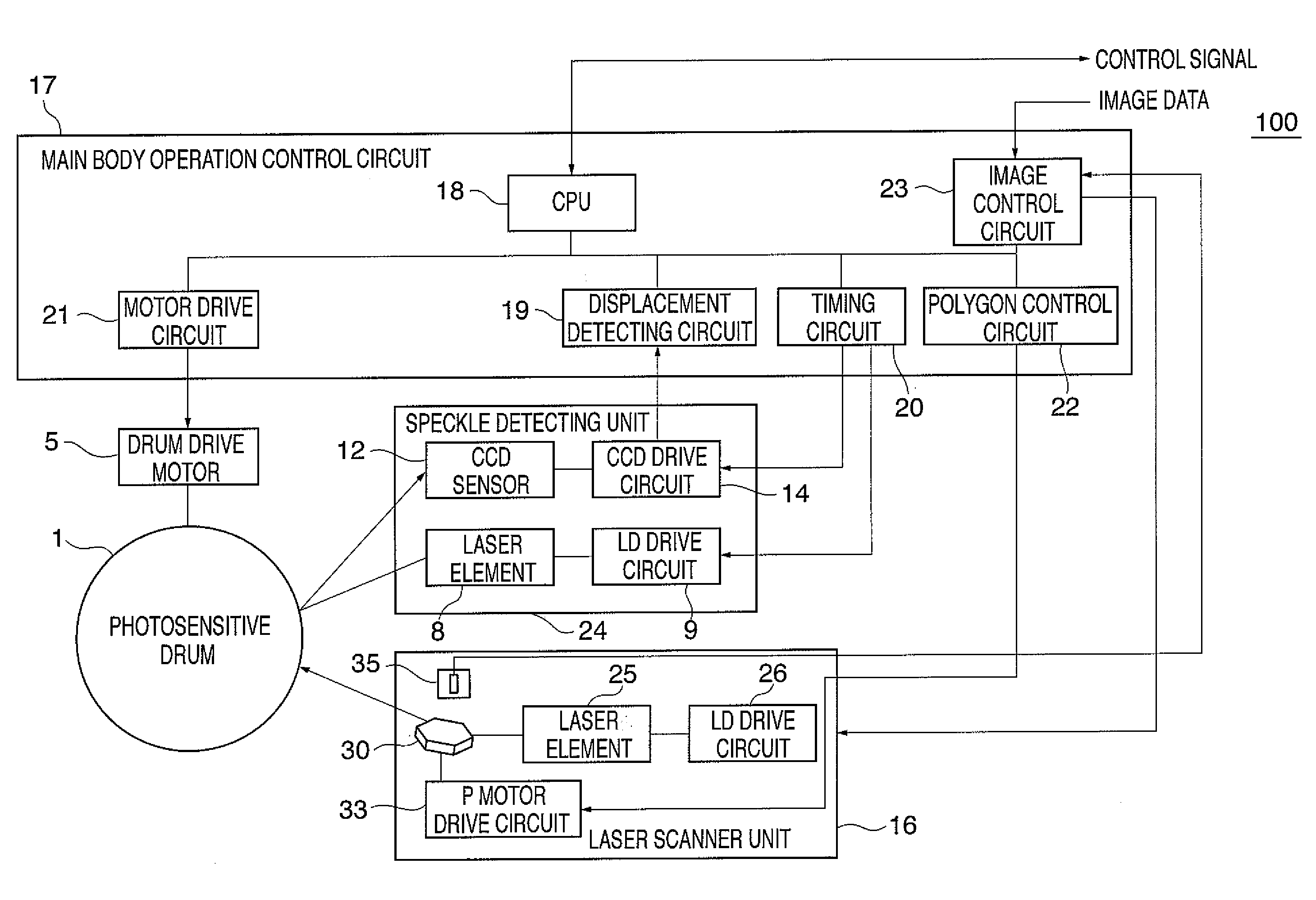
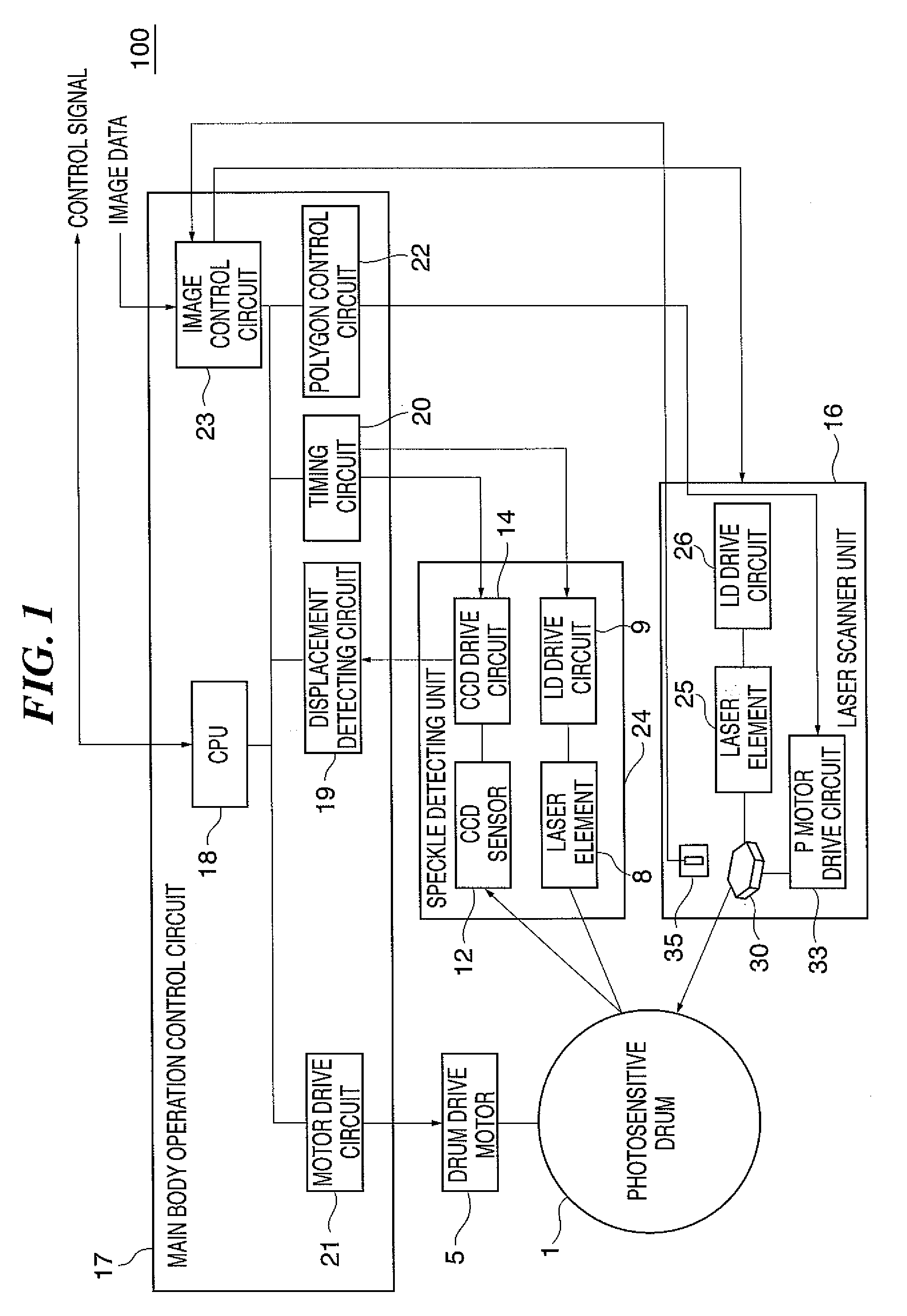
[0061]As described above, in the image forming apparatus 100 according to the present invention, speckle patterns indicative of the surface of the photosensitive drum 1 is detected at intervals of a predetermined sampling period, and the detected speckle patterns are compared with each other to detect the movement amount of the speckle pattern at a predetermined position on the surface of the photosensitive drum 1. The moving speed of the surface of the photosensitive drum 1 is calculated based on the movement amount of the speckle pattern at the predetermined position and the sampling period, and the rotational speed of the photosensitive drum 1 is controlled so that the calculated moving speed of the surface of the photosensitive drum 1 can be equal to a target value. As a result, the position at which an electrostatic latent image is formed can be controlled by controlling the rotational speed of the photosensitive drum 1 according to the moving speed of the surface of the photos...
second embodiment
[0062]Next, a description will be given of an image forming apparatus according to the present invention.
[0063]FIG. 4 is a schematic block diagram of the construction of the image forming apparatus 200 according to the second embodiment. FIG. 5 is a partial perspective view of the essential parts of the image forming apparatus 200.
[0064]The image forming apparatus 200 according to the second embodiment differs from the image forming apparatus 100 according to the above described first embodiment in the constructions of the laser scanner unit and the main body operation control circuit. In the following description, elements and parts corresponding to those of the image forming apparatus 100 according to the above described first embodiment are denoted by the same reference numerals, and description is omitted and only differences are described.
[0065]As shown in FIG. 5, the image forming apparatus 200 is provided with a laser scanner unit 201 in place of the laser scanner unit 16 of ...
fourth embodiment
[0085]Next, a description will be given of an image forming apparatus according to the present invention.
[0086]The image forming apparatus according to the fourth embodiment differs from the image forming apparatuses according to the above described first to third embodiments in that the laser element of the speckle detecting unit is removed, and the laser element of the laser scanner unit doubles as a laser element of the speckle detecting unit.
[0087]A description will now be given of an example of the image forming apparatus according to the present embodiment.
[0088]FIG. 7 is a perspective view of the essential parts of the image forming apparatus 400 according to the present embodiment. The image forming apparatus 400 differs from the image forming apparatus 200 according to the above described second embodiment in that the speckle detecting unit is disposed in the laser scanner unit, and the laser element of the laser scanner unit doubles as a laser element of the speckle detect...
PUM
 Abstract
Description
Claims
Application Information