Optical Device for Providing Prescription Correction to a Mirror
Inactive Publication Date: 2007-10-25
RYMNIAK CANDACE
View PDF7 Cites 3 Cited by
Summary
Abstract
Description
Claims
Application Information
AI Technical Summary
This helps you quickly interpret patents by identifying the three key elements:
Problems solved by technology
Method used
Benefits of technology
[0009]The lens situated in close proximity to the mirror provides a user who normally wears prescription eyeglasses with the appropriate corrective power to enable them to clearly see their face while providing enough working room for them to perfo
Problems solved by technology
People who wear prescription glasses have difficulty using mirrors for tasks such as applying cosmetics.
Their face, particularly
Method used
Image
Click on the blue label to locate the original text in one second.
Reading with bidirectional positioning of images and text.
Examples
example a
[0039]Lens power=2 diopters
[0040]Lens-to-object distance=23 mm
[0041]Lens-to-image distance=−42.5 mm
[0042]Magnification=1.85
[0043]FIG. 6B is a schematic representation of a viewer looking at an object at an equivalent distance as their lips where in FIG. 6A using a corrective lens placed where the mirror in FIG. 6A was, but with the mirror removed.
example b
[0044]Assuming the same power lens as in example A,
[0045]Power of lens=2 diopters
[0046]Lens-to-object distance=12.5.
[0047]Lens-to-image distance becomes=16.5 mm
[0048]Magnification=1.33
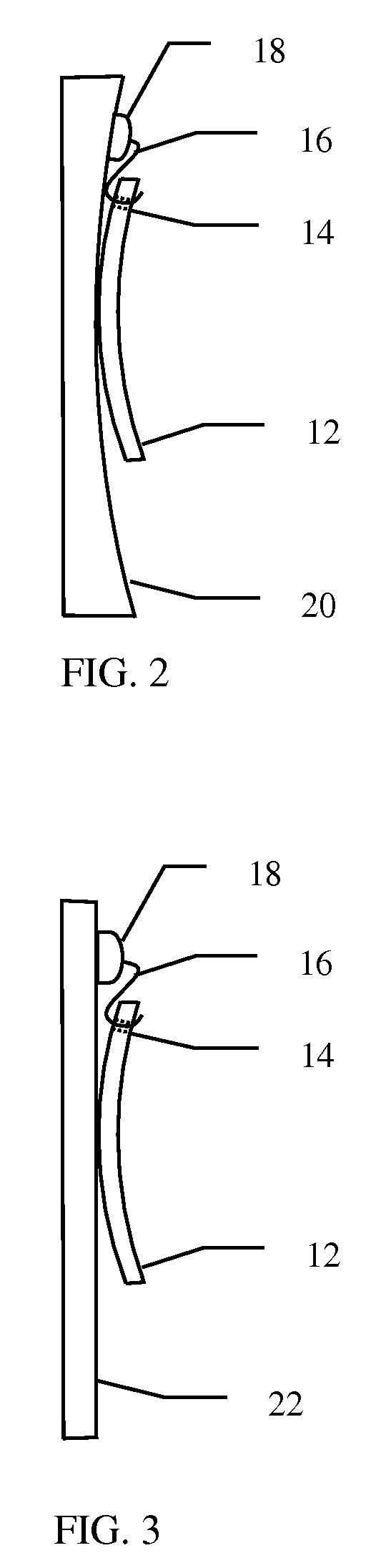
[0049]Example B demonstrates that by moving the lens 40 approximately half-way to the object, the magnification of the image is significantly reduced, almost to half. FIG. 6C, however, shows the actual optical arrangement that occurs in using the correction providing optical device 10. When the lens is moved to being in close proximity to the mirror 44, all imaging rays pass through the lens 52 twice. The lens 52, therefore, effectively has twice the power of lens 40.
example c
[0050]Assuming the same lens as in example A, but having twice the optical power because of the imaging rays traversing it twice.
[0051]Lens power=4 diopters
[0052]Lens-to-object distance=12.5 mm
[0053]Lens-to-image distance=25 mm
[0054]Magnification=2
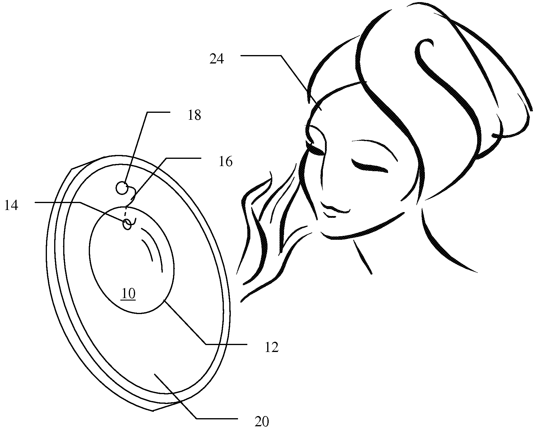
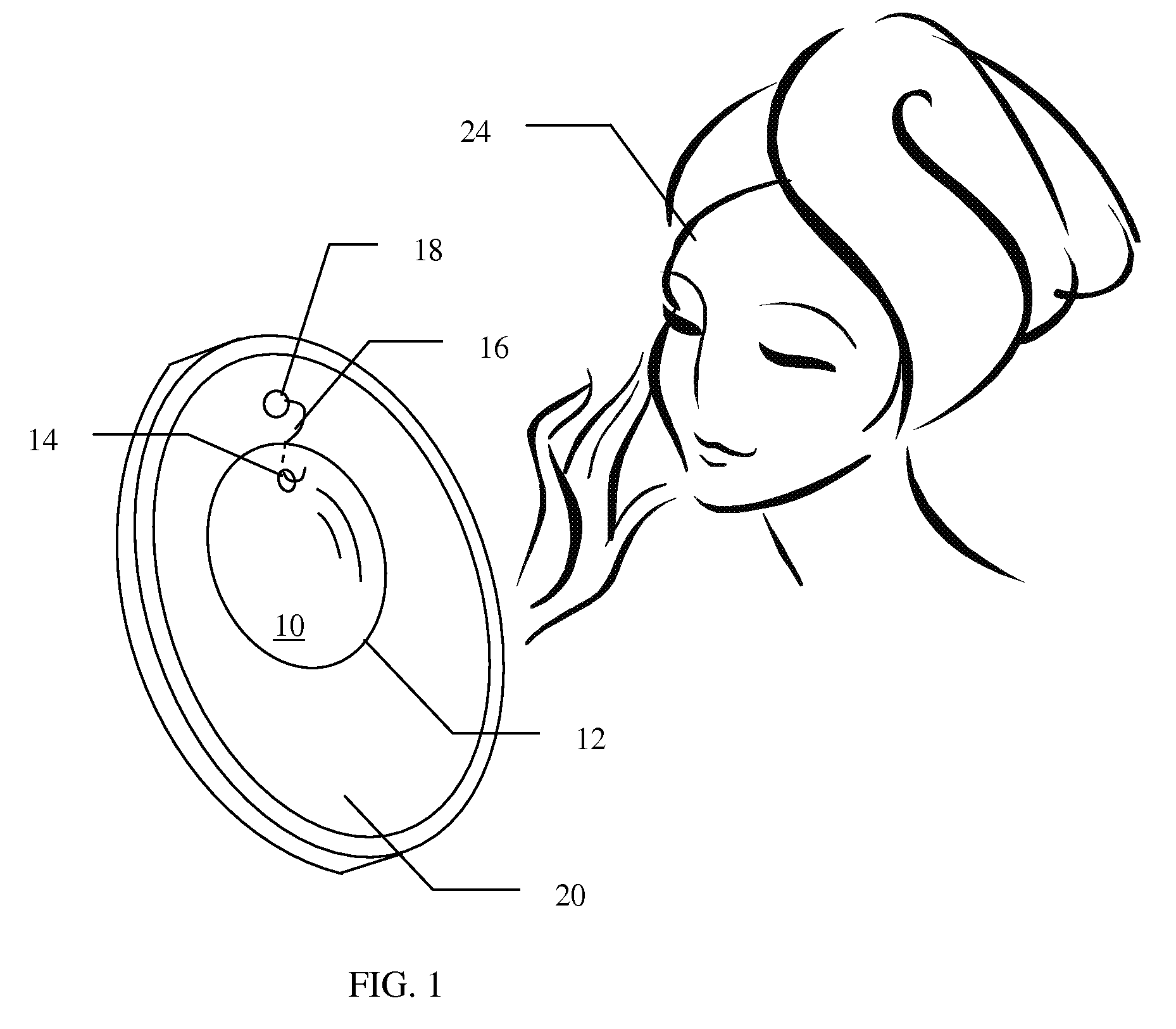
[0055]So same lens placed next to the mirror is slightly more effective in magnification at that position when looking at objects on the face such as, but not limited to the lips, than when worn as eye glasses because of double transit of the imaging rays through the lens. This has the interesting advantage of allowing a user 24 to use an eyeglass optical lens blank 12 having the same prescription as the lens in their reading glass for the correction providing optical device 10.
[0056]FIG. 4 is a cross-sectional drawing of a further preferred embodiment of the invention including a laterally pivoting extension arm. The flat mirror 22 of the correction providing optical device 10 of this embodiment may be removably attached to a wall 23 by a...
PUM
Abstract
An optical device for providing prescription correction to a mirror so that a person who normally wears prescription glasses may clearly see, and also have unobstructed access to, their face in order to apply makeup. A magnifying lens in the form of an eyeglass blank of an appropriate corrective power is removably attached to the mirror by means of a suction cup and a hook element. The magnifying lens has a hole joining its two refracting surfaces. One end of the hook element fits through the hole and the other end of the hook element is attached to the suction cup. The lens situated in close proximity to the mirror provides a user who normally wears prescription eyeglasses with the appropriate corrective power to enable them to clearly see their face while providing good working room for them to perform tasks such as applying their makeup.
Description
CROSS REFERENCE TO RELATED APPLICATIONS[0001]This application is related to, and claims priority from, U.S. Provisional Patent application No. 60 / 745,576 filed on Apr. 25, 2006 by Candace Rymniak entitled “Optical Apparatus for Providing Prescription Correction to a Mirror”, the contents of which are hereby incorporated by reference.FIELD OF THE INVENTION[0002]The present invention relates to optical devices, and more particularly to optical devices for providing prescription correction to mirrors to provide vision corrected, focused images at distances suitable for tasks such as applying cosmetics.BACKGROUND OF THE INVENTION[0003]People who wear prescription glasses have difficulty using mirrors for tasks such as applying cosmetics. Their face, particularly their eyes, is obstructed if they are wearing their glasses. Without their glasses, however, they cannot see their face clearly.[0004]Many people have attempted to address this issue. A fairly recent summary of these attempts ov...
Claims
Application Information
Patent Timeline
Application Date:The date an application was filed.
Publication Date:The date a patent or application was officially published.
First Publication Date:The earliest publication date of a patent with the same application number.
Issue Date:Publication date of the patent grant document.
PCT Entry Date:The Entry date of PCT National Phase.
Estimated Expiry Date:The statutory expiry date of a patent right according to the Patent Law, and it is the longest term of protection that the patent right can achieve without the termination of the patent right due to other reasons(Term extension factor has been taken into account ).
Invalid Date:Actual expiry date is based on effective date or publication date of legal transaction data of invalid patent.