Light Emitting Diode Lighting Package With Improved Heat Sink

a technology of led lighting and heat sink, which is applied in the direction of lighting and heating apparatus, semiconductor devices for light sources, lighting support devices, etc., can solve the problems of increased weight, increased cost of materials composing extrusions, and limited heat dissipation, so as to improve passive heat dissipation techniques

Inactive Publication Date: 2007-10-25
CREE INC
View PDF12 Cites 139 Cited by
  • Summary
  • Abstract
  • Description
  • Claims
  • Application Information

AI Technical Summary

Problems solved by technology

However, a few of the disadvantages of conventional fan based techniques include their cost, their unaesthetic appearance, and their production of fan noise.
Failings of this approach include added cost for materials composing the extrusions, added weight, and limited heat dissipation due to a build up of air pressure resulting from the heated air being trapped by the fins.

Method used


Image

  • Light Emitting Diode Lighting Package With Improved Heat Sink
  • Light Emitting Diode Lighting Package With Improved Heat Sink
  • Light Emitting Diode Lighting Package With Improved Heat Sink

Examples


Embodiment Construction

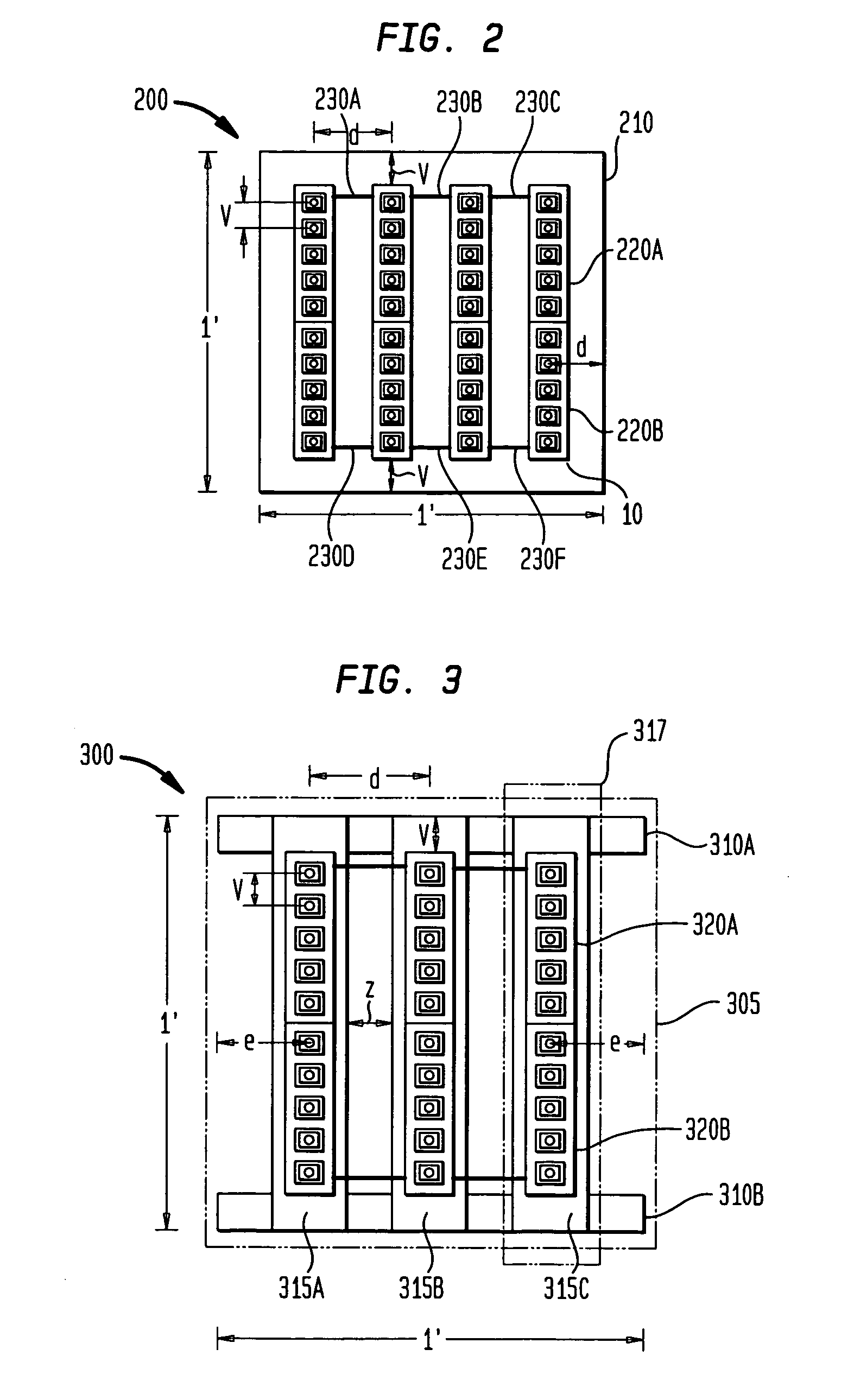
[0024]FIG. 2 shows a top view of a 1 foot×1 foot light emitted diode (LED) lighting package 200 in accordance with the present invention. The LED lighting package 200 includes a backing 210 of thermally conductive material such as aluminum. It is recognized that other thermally conductive materials such as ceramics, plastics, and the like may be utilized, aluminum is preferable because of its abundance and relative cheap cost. The construct of backing 210 as shown in FIG. 2 will be described further in connection with the discussion of FIG. 4.

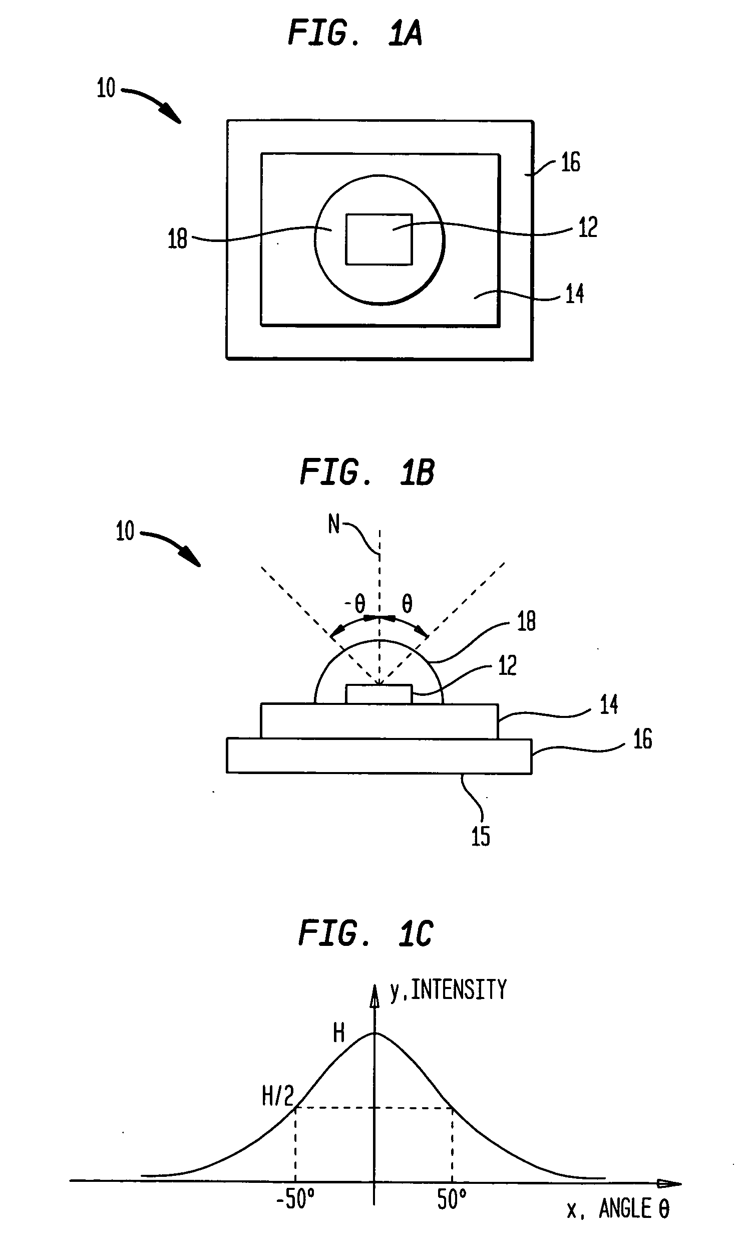
[0025] The LED lighting package 200 includes four columns of LEDs. Each column includes two printed circuit boards (PCB) such as PCB 220A and 220B. On each PCB, five LEDs such as LED 10 are mounted and are electrically connected in serial with each other. The total number of LEDs in LED lighting package 200 is forty. Each PCB includes a positive voltage terminal and a negative voltage terminal (not shown). The negative voltage terminal of PCB ...


PUM


Abstract

Improved lighting packages are described for light emitting diode (LED) lighting solutions having a wide variety of applications which seek to balance criteria such as heat dissipation, brightness, and color uniformity. The present approach includes a backing of thermally conductive material. The backing includes a cell structure. The cell structure comprises a plurality of hollow cells contiguously positioned in a side by side manner. The present approach also includes an array of LEDs. The array of LEDs is mounted to a printed circuit board (PCB). The PCB is attached to the cell structure to balance heat dissipation and color uniformity of the LEDs.

Description

FIELD OF THE INVENTION [0001] The present invention relates generally to improvements in the field of light emitting diode (LED) lighting fixtures, and, in particular, to methods and apparatus for improving the heat dissipation of LED lighting fixtures. BACKGROUND OF THE INVENTION [0002] As illustrated by FIGS. 1A, 1B and 1C, a common prior art LED mounting arrangement results in a substantial portion of the light output going upwardly in the direction of a normal to the top surface of a semiconductor photonic chip 12 as seen in FIG. 1B. As seen in FIG. 1A, a top view of an LED 10, the semiconductor photonic chip 12 is mounted on a substrate 14 which is in turn mounted on a bonding pad 16. The chip 12 is encapsulated beneath an optical lens 18 which focuses the light emitted by the chip 12. [0003]FIG. 1B shows a side view of LED 10 with a plurality of light rays relative to a normal, N, to the top surface of chip 12 illustrating the light emitted by chip 12 as it passes out of lens ...

Claims


Application Information

Patent Timeline
Patent Type & Authority Applications(United States)
IPC IPC(8): F21V29/00F21K99/00H01L33/00H01L33/48H01L33/54H01L33/64
CPCF21K9/00F21V29/89F21V29/70
Inventor VILLARD, RUSSEL G.
Owner CREE INC
Why Eureka
Try Eureka