Vehicle headlamp

a headlamp and projector technology, applied in the direction of point-like light sources, lighting and heating apparatus, etc., can solve the problems of difficult to difficult to partially reduce the illuminance of a portion of the region at inside the light distribution pattern, and the opening portion per se cannot adjust the intensity of transmitted light, etc., to achieve the effect of easy adjustment of the illuminance distribution

Inactive Publication Date: 2007-10-25
KOITO MFG CO LTD
View PDF4 Cites 54 Cited by
  • Summary
  • Abstract
  • Description
  • Claims
  • Application Information

AI Technical Summary

Benefits of technology

[0011]One or more embodiments of the invention provide a vehicle headlamp capable of easily adjusting an illuminance distribution in a light distribution pattern by overhead sign irradiating light, particularly capable of simply and firmly providing overhead sign irradiating light forming a dark portion having an illuminance lower than that of a surrounding thereof of a portion in the light distribution pattern in conformity with a countermeasure against glare of a vehicle running on an opposed lane or laws or regulations or the like.

Problems solved by technology

However, a light distribution pattern by the overhead sign irradiating light of JP-A-2003-297117 is determined by a contour shape of the opening portion formed at the portion at the vicinity of the upper end edge of the shade, the opening portion per se cannot adjust an intensity of transmitted light.
Therefore, it is difficult to adjust an illuminance distribution at inside of the light distribution pattern.
Particularly, it is extremely difficult to partially reduce an illuminance of a portion of a region at inside of the light distribution pattern even when a fine work is introduced to the shape of the opening portion.
Therefore, when there is brought about a request for forming a dark portion having an illuminance lower than that of a surrounding thereof of a portion in the light distribution pattern by the overhead sign irradiating light from, for example, a countermeasure against glare of a vehicle running on an opposed lane or laws or regulations or the like, it is difficult to deal therewith.

Method used


Image

  • Vehicle headlamp
  • Vehicle headlamp
  • Vehicle headlamp

Examples


Embodiment Construction

[0041]Exemplary embodiments of the invention will be described with reference to the accompanying drawings.

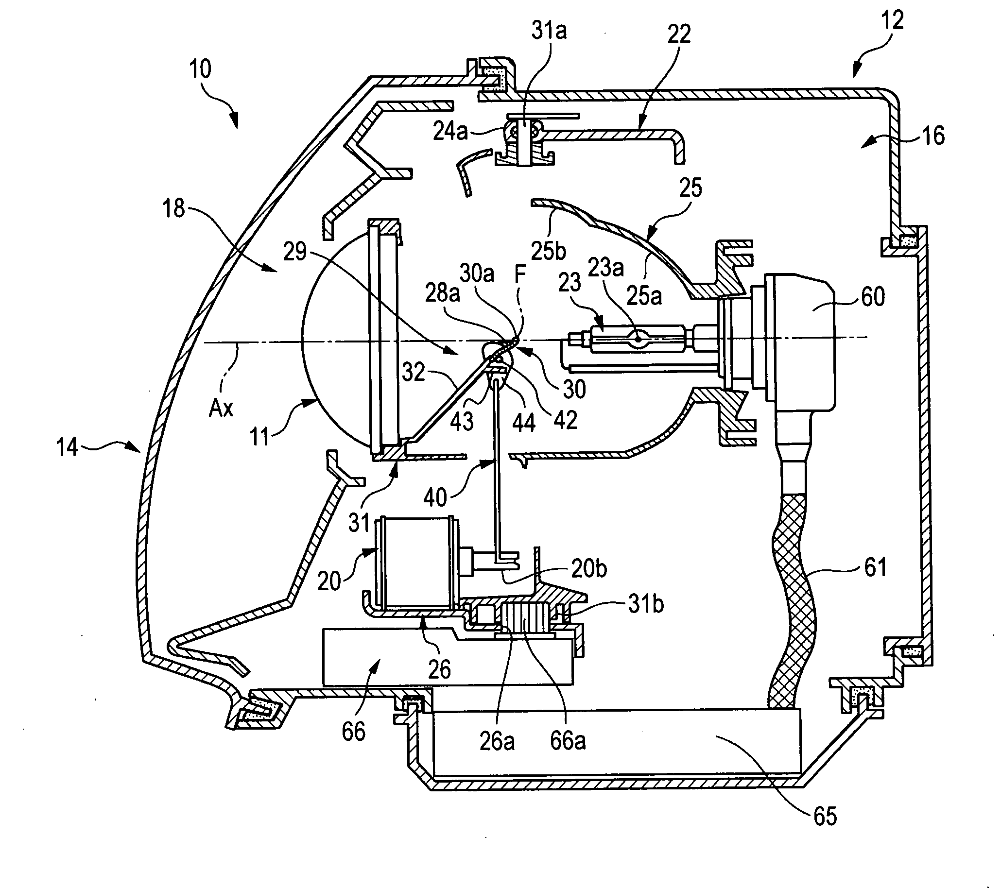
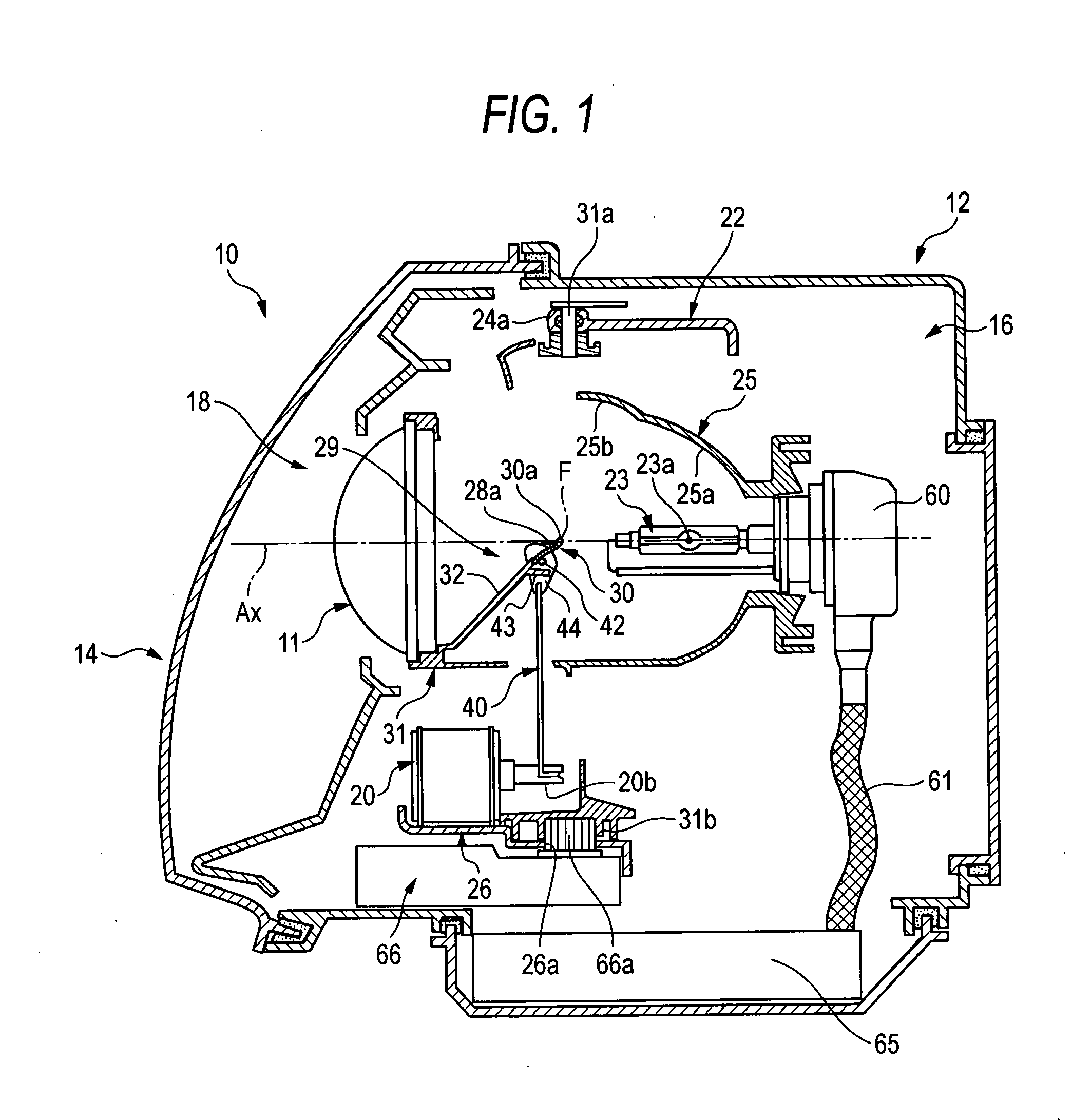
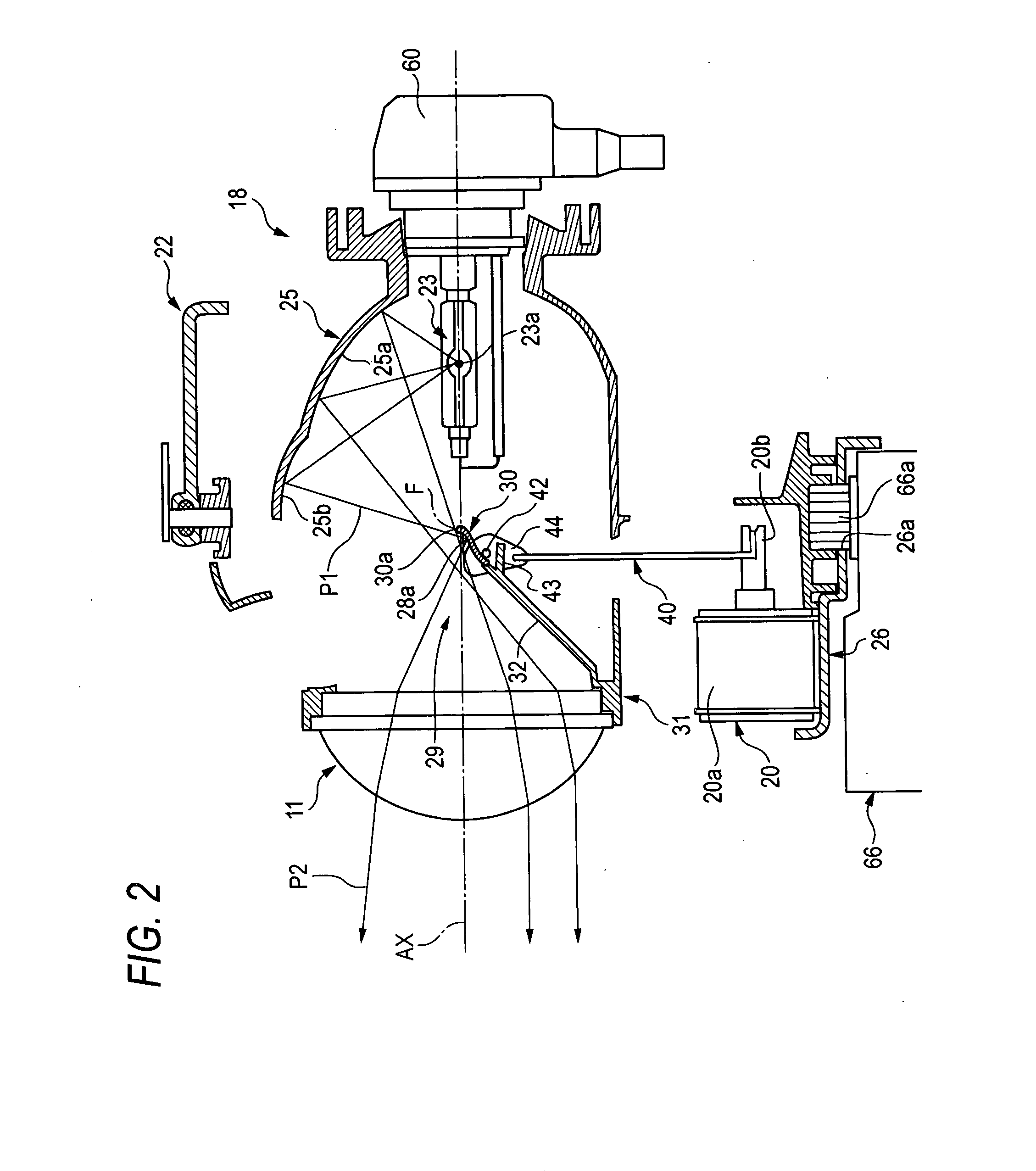
[0042]FIG. 1 is a vertical sectional view of a vehicle headlamp according to a first exemplary embodiment of the invention. FIG. 2 is an explanatory view of an operation when a movable shade is disposed at a blocking position in a lamp unit shown in FIG. 1. FIG. 3 is an explanatory view of an operation when the movable shade is disposed at a block alleviating position in the lamp unit shown in FIG. 1. FIGS. 4(a) and 4(b) are explanatory views of a light receiving face for an overhead sign in which the movable shade of the lamp unit shown in FIG. 1 is arranged on a front side, FIG. 4(a) is a front view of the light receiving face for the overhead sign, and FIG. 4(b) is a plane view thereof. FIG. 5(a) is a sectional view taken along a line A-A of FIG. 4(a). FIG. 5(b) is a sectional view taken along a line B-B of FIG. 4(a).

[0043]According to a vehicle headlamp 10 of the first exem...


PUM


Abstract

A lamp unit 18 is provided with a reflecting face 25b for an overhead sign and a light receiving face 28 for the overhead sign. The reflecting face 25b for an overhead sign reflects light from a light source 23a and is provided on an upper side of the light source 23a and rearward from a rear side focal point F of a projector lens 11. The light receiving face 28 for the overhead sign is provided on a front side of a movable shade 30 arranged between the projector lens 11 and the light source 23a. The light receiving face 28 forms overhead sign irradiating light P2 by reflecting light from the reflecting face 25b for the overhead sign to the projector lens 11. Illuminance reducer for reducing a portion of irradiating light is provided at a position of a vicinity of an upper end of the movable shade 30 of the light receiving face 28a for the overhead sign.

Description

[0001]This application claims foreign priority from Japanese Patent Application No. 2006-119905, filed on Apr. 24, 2006, the entire contents of which are hereby incorporated by reference.BACKGROUND OF THE INVENTION[0002]1. Field of the Invention[0003]The present invention relates to a projector type vehicle headlamp, particularly relates to a vehicle headlamp constituted to be able to irradiate an overhead sign (traffic sign).[0004]2. Related Art[0005]Generally, a vehicle headlamp of a projector type is constituted to reflect light from a light source arranged on an optical axis extended in a front and rear direction of a vehicle to a front side to be proximate to an optical axis by a reflector, and irradiate reflected light thereof to a front side of a lamp device by way of a projector lens provided on a front side of a reflector.[0006]Further, when the vehicle headlamp of the projector type is constituted for irradiating a low beam (passing beam), the beam is irradiated to the fro...

Claims


Application Information

Patent Timeline
Patent Type & Authority Applications(United States)
IPC IPC(8): B60Q1/00F21Y101/00
CPCF21S48/125F21S48/145F21S48/1778F21S48/1388F21S41/255F21S41/321F21S41/338F21S41/43F21S41/657F21S41/689F21S41/365F21W2102/18F21S41/172B60Q1/04F21S41/25
Inventor KINOSHITA, MASAOMATSUMOTO, AKINORITAJIMA, TAKEHIKO
Owner KOITO MFG CO LTD
Why Eureka
Try Eureka