Compression tissue repair apparatus and methods

a compression tissue and apparatus technology, applied in the field of compression tissue and minimally invasive surgical procedures, can solve the problems of reducing the elasticity and compatibility of the meniscus, failing with only minimal trauma, and wasting existing techniques

Inactive Publication Date: 2007-10-25
MASINI MICHAEL A
View PDF33 Cites 71 Cited by
  • Summary
  • Abstract
  • Description
  • Claims
  • Application Information

AI Technical Summary

Benefits of technology

[0011] In the preferred embodiment, the male and female portions of the fastener are constructed of a bioabsorbable material such as polylactic acid. The shaft of the male fastener is preferably ribbed or barbed, and the female portion of the fastener includes an aperture with features that engage with the ribs or barbs of the male portion, thereby facilitating a desired degree of compression as the portions engage. The head of the male fastener may also be angled for conformance with the outer surface of the tissue undergoing the repair.
[0012] The male portion may have an integral pointed tip, or such a tip may be provided through a separate introducer. In alternative embodiments, the male portion of the fastener includes a plurality of shafts and the female portion includes a corresponding set of receiving apertures. According tot yet a further alternative, the male portion includes a length of suture extending therefrom. As a further alternative, a length of suture material may connect multiple fasteners, thereby providing a knotless repair as the fasteners are advanced.

Problems solved by technology

The meniscus becomes less elastic and compliant and as a result may fail with only minimal trauma.
A torn meniscus will usually cause pain on the side of the knee proximate to the joint line.
Since existing techniques remain time-consuming, the need remains for a more expeditious approach to meniscal repair.

Method used


Image

  • Compression tissue repair apparatus and methods
  • Compression tissue repair apparatus and methods
  • Compression tissue repair apparatus and methods

Examples


Embodiment Construction

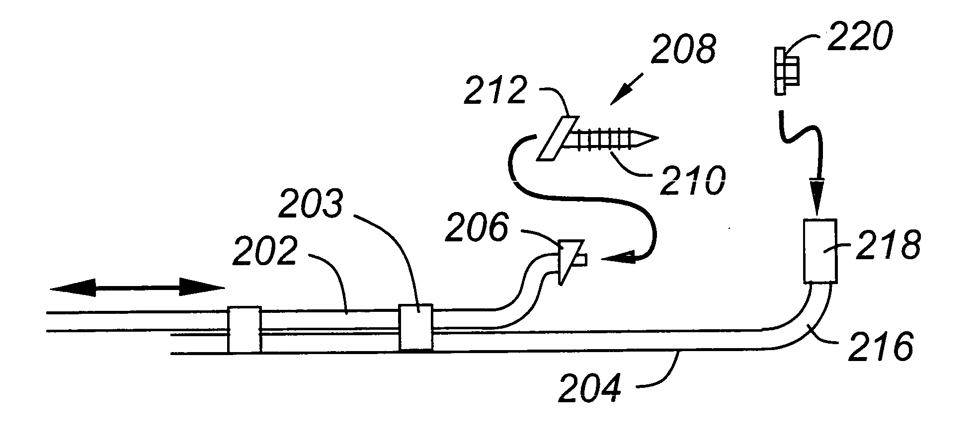
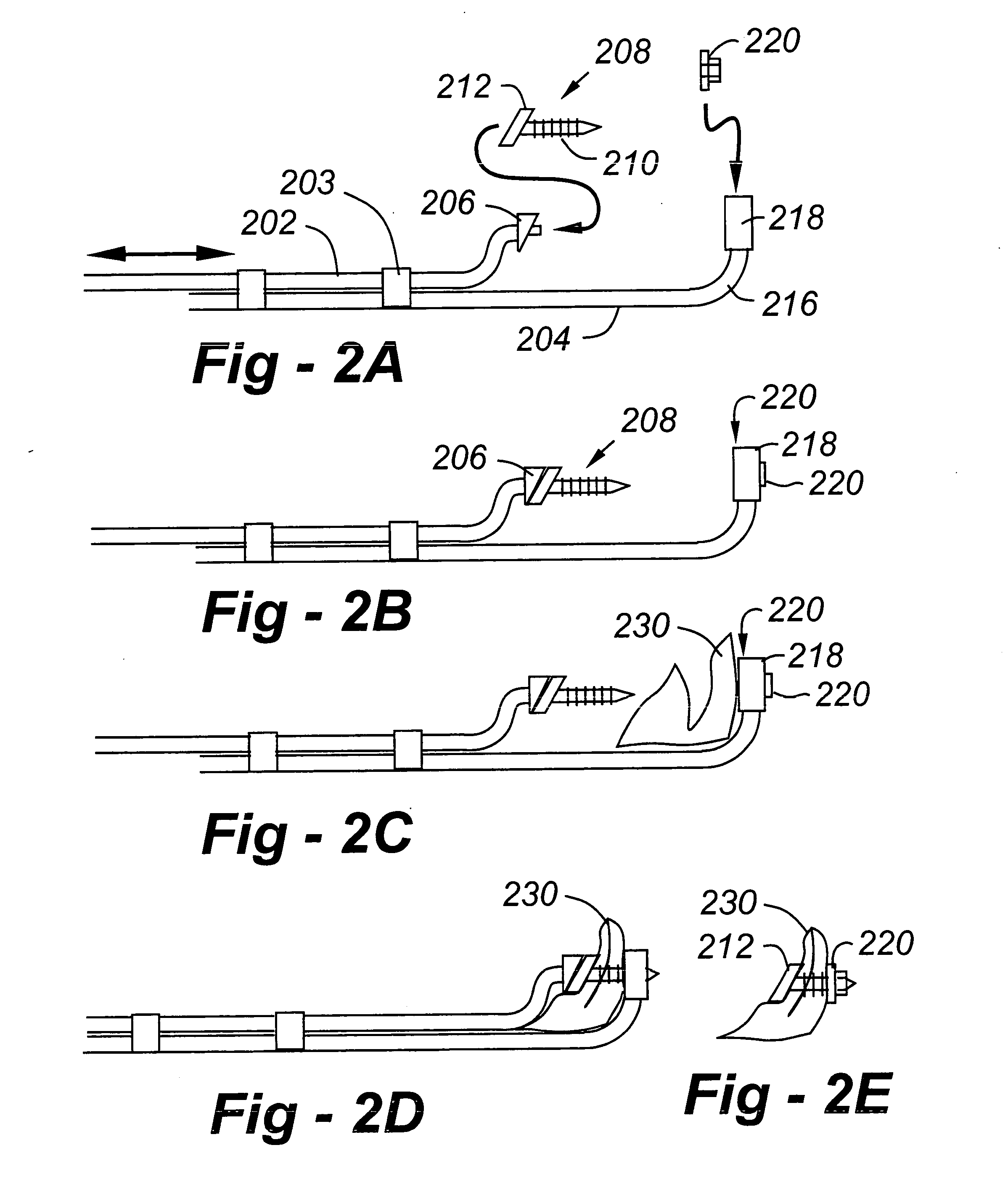
[0031] Turning now to the drawings, and having discussed FIGS. 1A and 1B, FIG. 2A presents a side-view drawing of an instrument according to the invention used for the repair of meniscus tissue. The instrument includes a lower arm 204, bent at 216, and terminating in a holder 218 for the female portion 220 of a fastener according to the invention. An upper arm 202, which is slideable relative to the lower arm 204, is physically configured to provide a holder 206 for the male portion 208 of the fastener. The arms may further include markings to indicate when engagement has occurred.

[0032] In the preferred embodiment, the fastener portions 208, 220, are preferably constructed of a bioabsorbable material, such as polylactic acid. The male portion of the fastener 208 includes a head 212 and a serrated shaft 120 terminating in a pointed end. The serrations may take the form of ribs, barbs, or other types of spaced-apart features. The female portion is washer-like, and includes one or mo...


PUM


Abstract

Instruments and methods facilitate expeditious minimally invasive surgical procedures. A tissue fastener is provided with a female portion and a male portion with a head and a shaft configured to engage with the female portion. A first elongated member is used to hold the female portion of the fastener behind tissue to be repaired. A second elongated member is used to hold the male portion of the fastener in front of tissue to be repaired in alignment with the female portion. The second elongated member is slideable relative to the first elongated member, allowing a user to pierce and compress the tissue as the male portion engages with the female portion. In the preferred embodiment, the male and female portions of the fastener are constructed of a bioabsorbable material such as polylactic acid. The shaft of the male fastener is preferably ribbed or barbed, the female portion of the fastener includes an aperture with features that engage with the ribs or barbs of the male portion, thereby facilitating a desired degree of compression as the portions engage. The head of the male fastener may also be angled for conformance with the outer surface of the tissue undergoing the repair.

Description

FIELD OF THE INVENTION [0001] This invention relates generally to meniscal repair and, in particular, to instruments and methods directed to expeditious minimally invasive surgical procedures. BACKGROUND OF THE INVENTION [0002]FIG. 1 is a simplified drawing of a knee joint. The femur is indicated at 102, the tibia at 103, the patella at 104, and the fibula at 120. The lateral and medial collateral ligaments are shown at 106, 108, respectively. The anterior and posterior cruciate ligaments are depicted at 110, 112. [0003] The meniscus is a horseshoe-shaped piece of cartilage situated between the weight bearing joint surfaces of the knee. It is triangular in cross section and is attached to the lining of the knee joint along its periphery. There are two menisci; the lateral meniscus 114 and the medial meniscus 116. The front third is referred to as the anterior horn, the back third the posterior horn, and the middle third the body. The menisci play an important role in protecting join...

Claims


Application Information

Patent Timeline
Patent Type & Authority Applications(United States)
IPC IPC(8): A61B17/08
CPCA61B17/04A61B17/0401A61B17/0469A61B17/064A61B17/0643A61B2017/0647A61B2017/0409A61B2017/0412A61B2017/0427A61B2017/0464A61B2017/0646A61B17/0682
Inventor MASINI, MICHAEL A.
Owner MASINI MICHAEL A
Why Eureka
Try Eureka