Messaging in a home automation data transfer system

a technology of home automation and data transfer system, which is applied in the field of home automation network organization, can solve the problems of large bandwidth, difficult upgrade of network and application software in the field, and large amount of time spent in training these developers

a technology of home automation and data transfer system, which is applied in the field of home automation network organization, can solve the problems of large bandwidth, difficult upgrade of network and application software in the field, and large amount of time spent in training these developers

US20070250592A1Inactive Publication Date: 2007-10-25INTERMATIC

Image

  • Messaging in a home automation data transfer system
  • Messaging in a home automation data transfer system
  • Messaging in a home automation data transfer system

Examples


Embodiment Construction

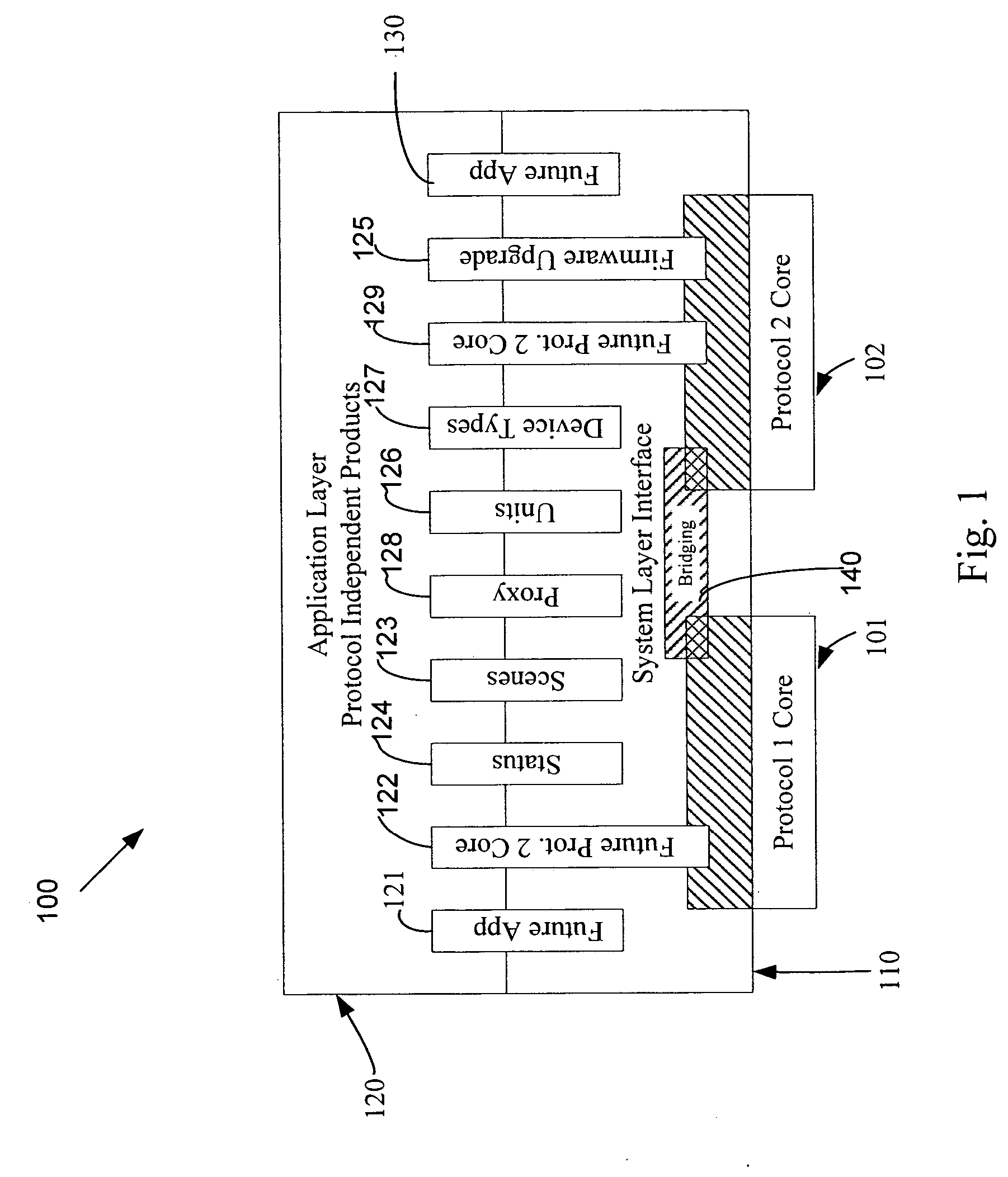
[0025]FIG. 1 illustrates a network abstraction block diagram 100. A network transport layer, such as a first protocol network core 101 or a second protocol network core 102 may reside at the lowest level of the network layers. The network transport layer 101 may include hardware and / or software for implementing network transport functions for the network. The first protocol network core 101 and / or the second protocol network core 102 may provide transparent transfer of data between end users, relieving the upper layers from any concern with providing reliable and cost-effective data transfer. The transport layer controls the reliability of a given link. Some transport protocols may be connection oriented, where the transport layer may track packets and retransmit those that fail. The first protocol network core 101 and / or the second protocol network core 102 may implement protocols such as the Z-Wave® home automation transport protocol. Other network protocols, such as commercial, i...


PUM


Abstract

An automation network includes automation network devices connected to the network and a system layer interface that interfaces with a transport layer and an application layer of the automation network. The system layer interface includes messaging command libraries configured to implement human-readable messages for the automation network devices, where the automation network devices include at least one message output device. The system layer interface may provide commands and functions to establish messaging in the network, the length of supported messages, and scrolling of messages on output display devices.

Description

PRIORITY CLAIM [0001] The present application claims the benefit of priority of U.S. Provisional Application Ser. No. 60 / 733,514, “Data Transfer System,” filed Nov. 4, 2005, the contents of which are incorporated by reference in their entirety herein. RELATED APPLICATIONS [0002] This application is related to U.S. patent application Ser. No. ______, “Device Types and Units for a Home Automation Data Transfer System,” (Atty. Docket No. 1390.947); U.S. patent application Ser. No. ______, “Proxy Commands and Devices for a Home Automation Data Transfer System,” (Atty. Docket No. 1390.948); U.S. patent application Ser. No. ______, “Application Updating in a Home Automation Data Transfer System,” (Atty. Docket No. 1390.949); U.S. patent application Ser. No. ______, “Remote Device Management in a Home Automation Data Transfer System,” (Atty. Docket No. 1390.951); and U.S. patent application Ser. No. ______, “Protocol Independent Application Layer for an Automation Network,” (Atty. Docket N...

Claims


Application Information

Patent Timeline
25 Oct 2007
Publication
US20070250592A1
IPC
G06F15/16
CPC
H04L12/66
Inventors
RECKAMP, STEVEN; DINESCU, MIKY