Rotary cleaning head

a rotary cleaning head and cleaning head technology, applied in the field of floor cleaning machines, can solve the problems of ineffective squeegee-equipped vacuum heads, inconvenient cleaning of soft surfaces, and inability to use rotary cleaning heads, etc., and achieve the effect of simple, economical and effective cleaning

Active Publication Date: 2007-11-01
MONSON CHARLES B
View PDF20 Cites 29 Cited by
  • Summary
  • Abstract
  • Description
  • Claims
  • Application Information

AI Technical Summary

Benefits of technology

[0003]There has been a long felt need for a simple, economical and effective rotary cleaning head for floor cleaning machines that may solve some of the problems associated with conventional rotary cleaning heads.

Problems solved by technology

Such a rotary cleaning head would not be useable for cleaning soft surfaces, such as carpeting, because the cleaning bristles or scrubbing pads would tend to snag or untwist the carpet fibers, and the squeegee equipped vacuum heads would not be very effective on a carpeted surface.
Such a rotary cleaning head would not be very useable for cleaning hard surfaces, since it would lack squeegees and scrubbing bristles or scrubbing pads.

Method used


Image

  • Rotary cleaning head
  • Rotary cleaning head
  • Rotary cleaning head

Examples


Embodiment Construction

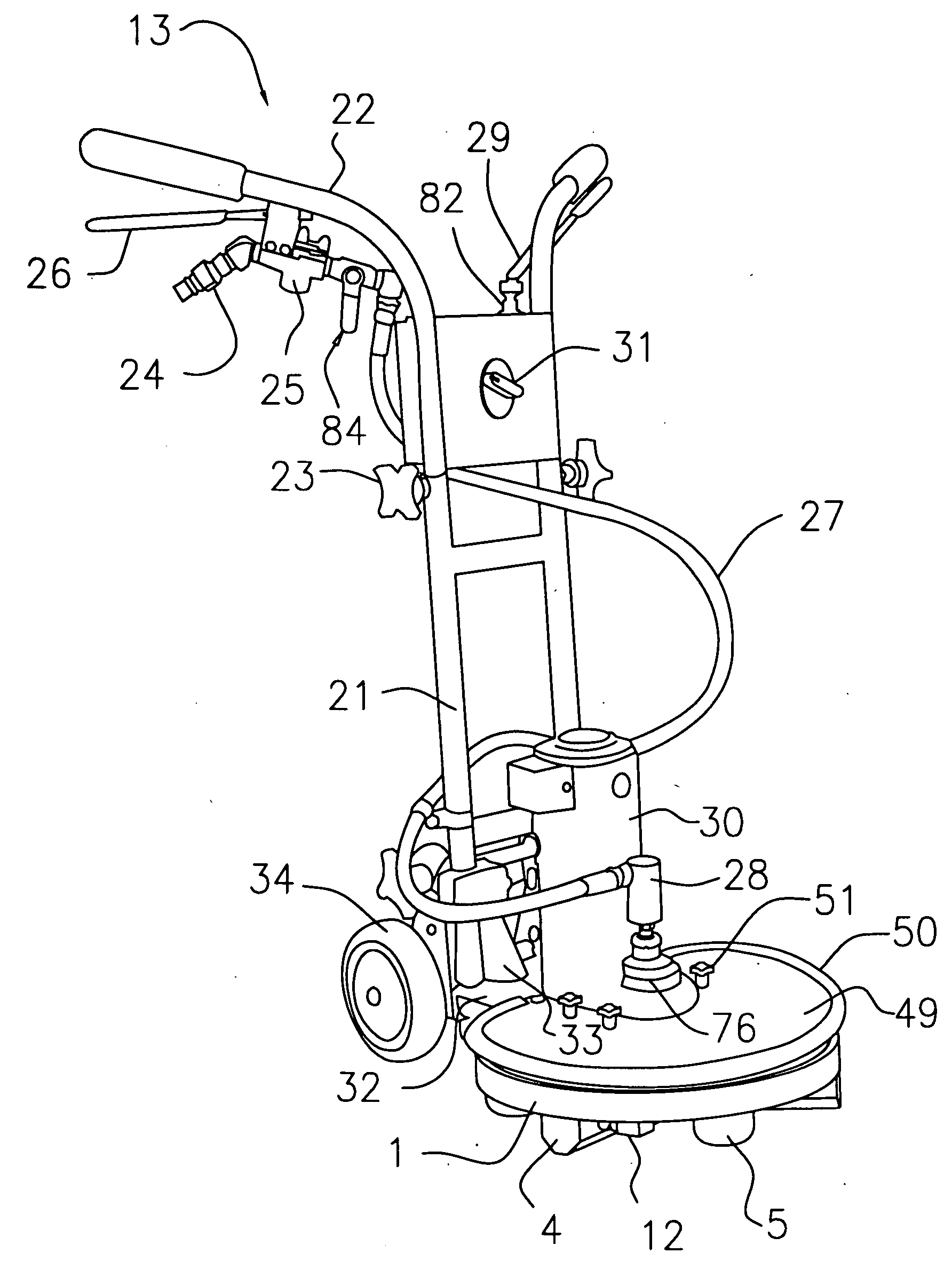
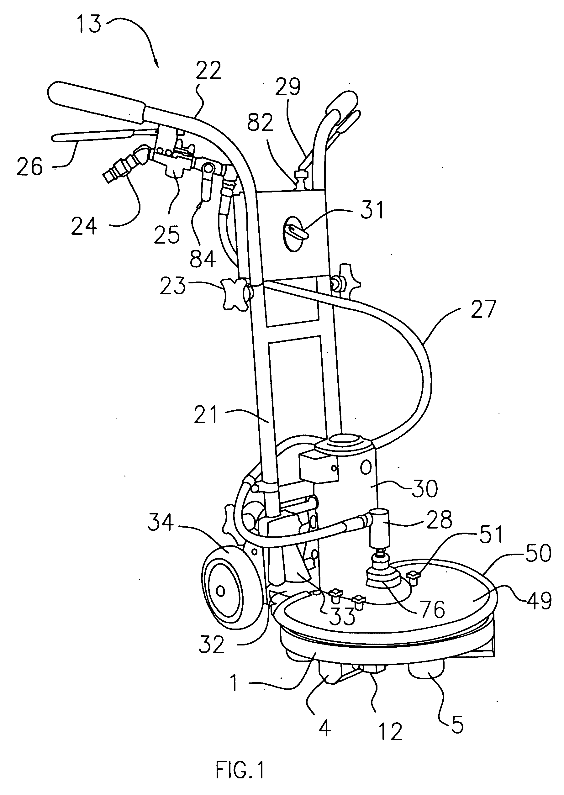
[0025]Turning now to FIG. 1, the rotary cleaning head 1 of the present invention may be used with any suitable floor cleaning machine 13. A conventional floor cleaning machine 13 may typically comprise any suitable frame 21 and a pair of handles 22. The handles 22 may be made height adjustable in any suitable way, such as by telescoping them within frame 21 and selectively locking them in place with any suitable locking mechanism, such as a pair of locking knobs 23.

[0026]One of the handles 22 may carry a fluid coupling 24 to which a source of cleaning fluid may be attached. Any suitable cleaning fluid may be used, such as water for example, to which may be added any suitable cleaning agents such as detergents, anti-foam agents, or surfactants, for example.

[0027]Any suitable valve mechanism, such as a valve 25 actuated by a control lever 26, may be providing for controlling the flow of cleaning fluid to the rotary cleaning head 1 through a supply line 27 and a rotary fluid coupling 2...


PUM


Abstract

A rotary cleaning head that may have a main disc, a cover, and vacuum heads. The cover may define an axially aligned central vacuum opening; and the main disc and cover may define therebetween a vacuum distribution hub and vacuum channels for distributing vacuum from the cover's central vacuum opening to the vacuum slots in the vacuum heads. A dual purpose seal may provide a seal between the cover and the main disc, and may also define at least part of the vacuum hub and vacuum channels. The vacuum heads may have vacuum notches or ridges that may help to collect and direct the cleaning fluid on at least part of the vacuum heads' outer surfaces into vacuum heads' vacuum slots. The rotary cleaning head may be modified to clean either hard surfaces or soft surfaces.

Description

CROSS REFERENCE TO RELATED APPLICATION[0001]This application claims the benefit under 35 U.S.C. 119(e) of U.S. Provisional Application No. 60 / 795,544 filed on Apr. 27, 2006.BACKGROUND OF THE INVENTION[0002]The present invention relates to floor cleaning machines for hard or soft surfaces; and more particularly, it relates to rotary cleaning heads for floor cleaning machines.BRIEF SUMMARY OF THE INVENTION[0003]There has been a long felt need for a simple, economical and effective rotary cleaning head for floor cleaning machines that may solve some of the problems associated with conventional rotary cleaning heads.[0004]For example, one problem that may be solved by the present invention is how to provide a rotary cleaning head that distributes vacuum to the rotary cleaning head's vacuum heads in a simple, effective, and efficient way, despite the rotation of the rotary cleaning head during use. The present invention may solve this problem by providing a rotary cleaning head that may ...

Claims


Application Information

Patent Timeline
Patent Type & Authority Applications(United States)
IPC IPC(8): A47L5/10
CPCA47L11/03A47L11/302A47L11/4036A47L11/4088A47L11/4075A47L11/4077A47L11/4044
Inventor MONSON, CHARLES B.
Owner MONSON CHARLES B
Why Eureka
Try Eureka