
Liner hanger tool with re-latchable cementing bushing

Active Publication Date: 2007-11-01
DRIL QUIP
View PDF3 Cites 33 Cited by
  • Summary
  • Abstract
  • Description
  • Claims
  • Application Information

AI Technical Summary

Benefits of technology

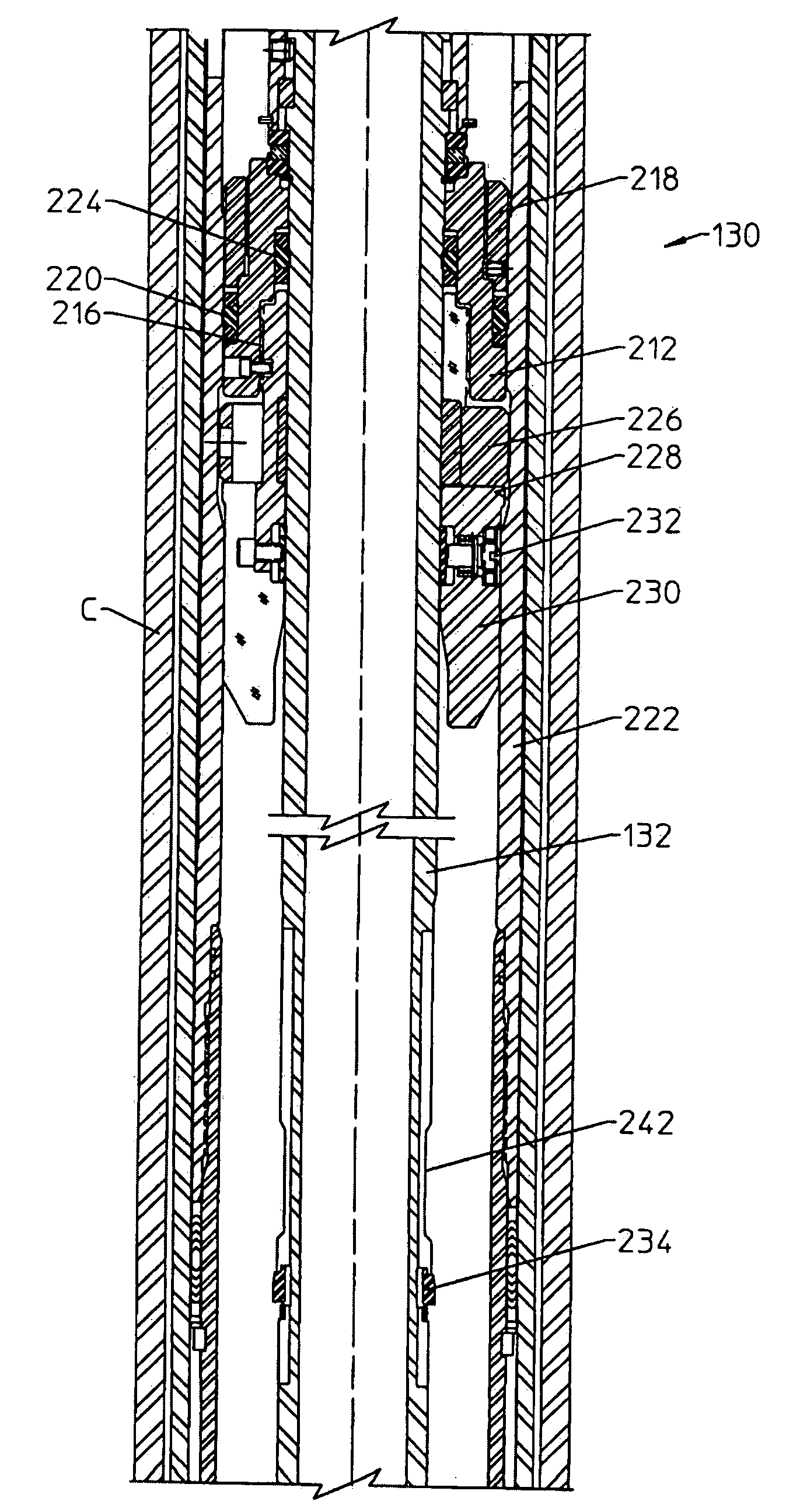
[0008]The liner hanger assembly also includes a cementing bushing which may be re-inserted into the liner in the event that the running string is raised above the liner, thereby allowing pressure integrity to be re-established. The cementing bushing may be reinserted into the liner if, after setting and releasing from the liner, the setting tool is picked up out of the liner hanger while checking for the release of the running tool, or if upward movement of the drill string while cementing lifts the running tool above the liner hanger. A circumferential loading ring enhances the cementing pressure capability of the bushing, which has improved capacity and reliability, thereby providing more flexibility to the operator.
[0009]In one embodiment, a cementing bushing for sealing between a liner hanger and liner hanger running tool comprises a bushing body including a radially outward seal for sealing with the liner hanger and a radially inward seal for sealing with the running tool. A first C-ring or other locking member is axially moveable with the bushing body and radially moveable for axially interconnecting and disconnecting the bushing body and the liner hanger. A slick joint supported on the running tool allows the running tool to move upward while sealing with the radially inner seal of the bushing. A second C-ring or other locking member is positioned on the slick joint, and expands to connect the bushing to the slick joint when moved upward. When the slick joint is subsequently lowered and the first C-ring begins to reenter the groove, the buttons are forced radially inward, collapsing the second C-ring to disconnect the bushing from the slick joint. The first locking member is thus reengaged with the liner hanger and the second locking member releases the bushing from the slick joint.

Problems solved by technology

These lugs may be small and limit the cementing pressure capability of the packoff bushing.
If the operator picks up the running tool above a length of the slick joint, the packoff bushing may disengage from the liner hanger and cause a cementing failure.
The entire assembly may then have to be retrieved, since it is not possible to regain pressure integrity.
More particularly, the cementing bushing disclosed in the '398 patent may be pulled out of the liner and re-stabbed into the liner, although the possibility of pressure trapped below the cementing bushing detracts from the reliability of the system.

Method used


Image

  • Liner hanger tool with re-latchable cementing bushing
  • Liner hanger tool with re-latchable cementing bushing
  • Liner hanger tool with re-latchable cementing bushing

Examples


Embodiment Construction

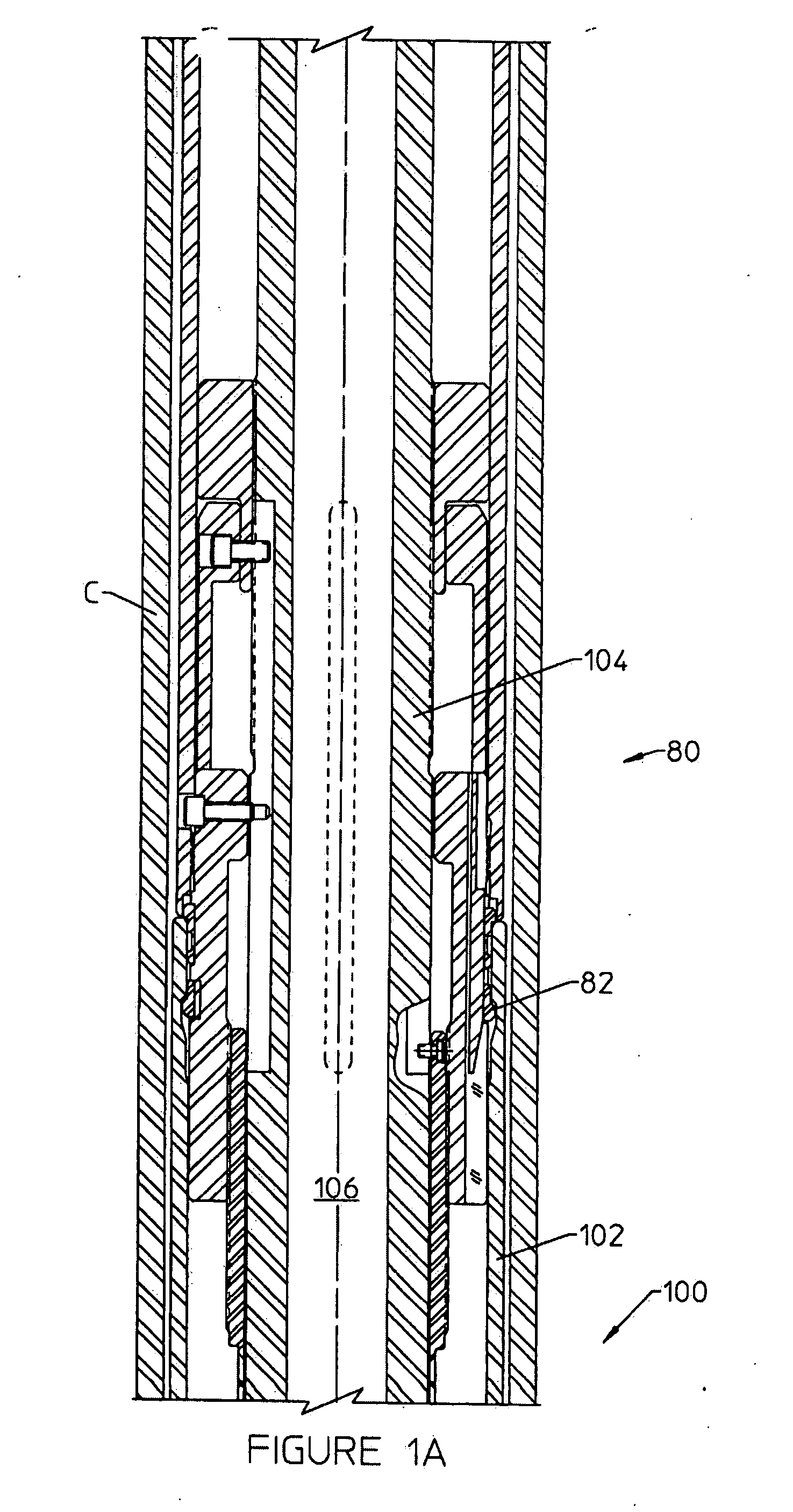
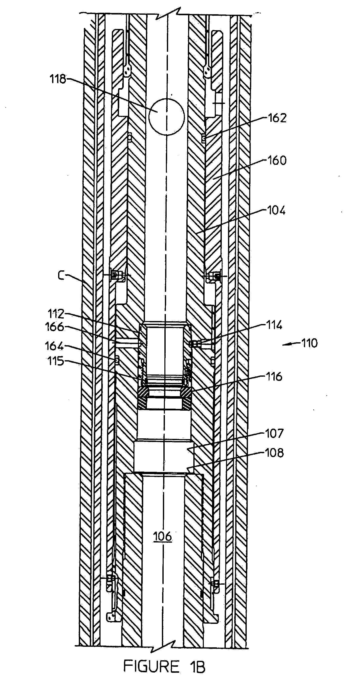
[0019]FIG. 1, which consists of FIGS. 1A-1G, illustrates one embodiment of a liner hanger tool 100 with two C-ring seat subassemblies each for seating with a closure member in a liner hanger application. An upper C-ring seat subassembly 110 is shown in FIG. 1B, and a lower C-ring seat subassembly 170 is shown in FIG. 1D. Other than components associated with seating and releasing the closure member, the primary components of the liner hanger running tool 100 as shown in FIG. 1 include a running tool tieback locking mechanism 80 (FIG. 1A), a slip release assembly operatively responsive to the upper C-ring seat assembly 110, packer setting ring 180 (FIG. 1C), a liner hanger release assembly 175 operatively responsive to the lower C-ring seat assembly (FIG. 1D), a cementing bushing 130 (FIG. 1E), and a ball diverter 140 and plug release assembly 150 (FIG. 1G). FIG. 1E illustrates the packer 122 and FIG. 1F illustrates the slip assembly 120, which are not part of the running tool retrie...


PUM


Abstract

A liner hanger assembly comprises a tool mandrel 104 suspended on a running string, and a slip assembly 120 for engaging a casing to support the liner hanger assembly and liner from the casing. The release assembly 175 releases the set liner hanger from portions of the assembly to be retrieved to the surface. As cementing bushing 130 is releasable and reinsertable into the liner, and includes a circumferential loading ring 226.

Description

RELATED CASE[0001]The present application claims priority from U.S. Ser. No. 60 / 795,549 filed Apr. 27, 2006.FIELD OF THE INVENTION[0002]The present invention relates to downhole tools with sealing components to conduct cementing operations. More particularly, the present invention relates to a liner hanger assembly for hanging a liner in a well, and to a lockable and re-latchable cementing bushing.BACKGROUND OF THE INVENTION[0003]A cementing bushing, sometimes referred to as a packoff bushing, is used in a liner hanger assembly to seal between the liner and the running tool, which is lowered into the well on a running string. Once properly lowered, cement is discharged through the running string and around the liner in the well bore. The cementing bushing thus provides for the required increase in fluid pressure to pump cement in the well, and subsequently to selectively break the seal between the liner and the running tool.[0004]Prior art cementing bushings use multiple lugs protru...

Claims


Application Information

Patent Timeline
IPC IPC(8): E21B23/00
CPCE21B43/10E21B23/01E21B33/13
Inventor REIMERT, LARRY E.YOKLEY, JOHN M.
Owner DRIL QUIP
Learn More