Method for the production of scaffolds for tissue engineering, comprising the useof an anchoring unit, and scaffold produced therewith

Inactive Publication Date: 2012-07-26
KONINKLIJKE PHILIPS ELECTRONICS NV
View PDF1 Cites 7 Cited by
  • Summary
  • Abstract
  • Description
  • Claims
  • Application Information

AI Technical Summary

Benefits of technology

[0010]It is another object of the present invention to provide a process for labelling a scaffold for tissue engineering, or an engineered tissue or organ, which provides for more flexibility in terms of imaging options than the methods from the prior art.
[0011]It is another object of the present invention to provide a

Problems solved by technology

However, the cells growing on the scaffold as well as the scaffolds itself provide little, or even no, contrast compared to the surrounding tissues in clinically relevant imaging modalities such as CT, MRI, X-Ray, scintigraphy and/or Ultrasound imaging, and can therefore hardly be visualized.
This approach, however, has some serious drawbacks, one of them being the fact that the type of label which is used must be invariably determined at the time the scaffold is produced.
Under some circumstances, a given label may however turn out unsuitable, e.g., for a given imaging device, or because it elicits an immune response in a given patient.
Furthermore, label bleaching may occur.
Another disadvantage may arise from permanent in-situ release of the respective label, or its matabolic products, once

Method used


Image

  • Method for the production of scaffolds for tissue engineering, comprising the useof an anchoring unit, and scaffold produced therewith
  • Method for the production of scaffolds for tissue engineering, comprising the useof an anchoring unit, and scaffold produced therewith
  • Method for the production of scaffolds for tissue engineering, comprising the useof an anchoring unit, and scaffold produced therewith

Examples


Example

Example 1

Labelling of a Scaffold with Click Chemistry Comprising a Covalently Bound Anchoring Unit

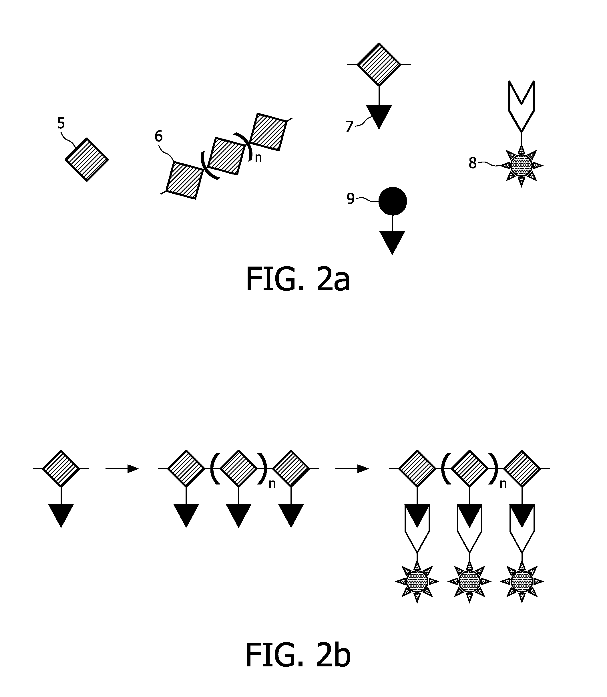
[0189]A copolymer of ε-caprolactone and α-bromo-ε-caprolactone (or a pure α-bromo-ε-caprolactone) is being produced, which serves as a polymer for formation of the scaffold. This process is described in examples 1.1.-1.3. Then the Br-groups of the copolymer are being substituted by azide (N3)-groups, the latter being the anchoring units of the present invention. This process is described in example 1.4. The copolymer can undergo a scaffold formation process, e.g., by electrospinning, prior or after the substitution process. Labelling agents are being bound to the anchoring units by means of a staudinger reaction.

[0190]1.1. Synthesis of α-bromocyclohexanone

[0191]α-bromocyclohexanone is synthesized according to the following procedure: To a stirred mixture of 30 g (0.306 mol) of cyclohexanone and 200 mL of distilled water, 49 g (0.306 mol) of bromine is added dropwise over a period of 5 h...

Example

Example 2

Labelling of an Oligonucleotide Binding Agent with 18F

[0204]An oligonucleotide as shown in FIG. 5 is labelled at its 5′-end with 18F according to the method of Kuhnast 2003. 18F is preferably used in positron emission tomography (PET) and scintigraphy (see table 1). A complementary oligonucleotide is anchored to a scaffold material by means according to the art, thus serving as an anchoring unit according to the invention. Methods to bind an oligonucleotide to a silicate surface or to a polymer surface are for example known from the literature related to the manufacture of biochips.

Example

Example 3

Labelling of a Scaffold by Means of Gd-Labelled oligonucleotides

[0205]3.1. Synthesis of the DNA-Particle-Component

[0206]Au (Gold) particles can be prepared as described in literature (Grabar et al. (1995)). These particles are easily modified with oligonucleotides, which are functionalized with alkane thiols at one of their termini, e.g., the 5′ terminus. Here, a solution of 1.5 ml (17 nM) Au colloids (13 nm Ø) is treated for 24 h with 460 μl (3.75 μM) SH-5′-Oligonucleotides-3′ of the following kind (sequence is randomly selected here, i.e., any other sequence will do as well):

3′-GCTATCTGGCTATCTGTATCTGTTTTTTT-5′-SH

[0207]in order to provide DNA-Gold-components In such way, an anchoring unit comprising an oligonucleotide as a binding agent is obtained. See FIG. 10 for an illustration of said process.

[0208]3.2. Synthesis of the DNA-Gd-Label Component

[0209]1 μmol amine-modified oligonucleotide of the following kind (part of sequence is complementary to the above sequence):

H2N-5...


PUM

PropertyMeasurementUnit
Phaseaaaaaaaaaa
Biodegradabilityaaaaaaaaaa
Covalent bondaaaaaaaaaa

Abstract

The present invention relates to a method for the production of scaffold materials and/or scaffolds for tissue and/or organ engineering, said method comprising the addition of at least one anchoring unit for a labelling agent, to at least one scaffold material and/or to at least one scaffold.

Description

FIELD OF THE INVENTION[0001]The present invention is related to scaffold materials and scaffolds for tissue engineering and organ engineering. More particularly, the present invention is related to the labelling of scaffold materials and scaffolds, which serve as contrast agents for medical imaging means, like CT, MRI, X-Ray, ultrasound, scintigraphy and the like.BACKGROUND OF THE INVENTION[0002]Tissue engineering is a relatively young discipline which aims at producing, in the laboratory, tissues, or organs, which may then be used to repair, or replace, defective tissues, or organs, of a patient.[0003]In many cases, the said tissues, or organs, are being produced with help of a scaffold, this being a three-dimensional matrix which the cells use as basis for their growth, and division, either in vitro or in vivo. Such scaffold needs to mimic the in vivo milieu, and enable cells to influence their own microenvironment. In order to do so, it needs to allow cell attachment and migratio...

Claims


Application Information

Patent Timeline
IPC IPC(8): C08G63/91B29C47/00
CPCA61K49/0002A61K49/085A61K49/126A61K51/0491A61L2300/44A61L27/54A61L27/58A61L31/148A61L31/18A61K51/065
Inventor HALTER, DAVIDKURT, RALPHPEETERS, EMIELPENTERMAN, ROELBROER, DIRK JANLAMERICHS, RUDOLF MATHIAS JOHANNES NICOLAAS
Owner KONINKLIJKE PHILIPS ELECTRONICS NV
Why Eureka
Try Eureka