Carotid sheath with thin-walled shaft and variable stiffness along its length

Inactive Publication Date: 2012-10-18
FISCHELL INNOVATIONS
View PDF4 Cites 7 Cited by
  • Summary
  • Abstract
  • Description
  • Claims
  • Application Information

AI Technical Summary

Benefits of technology

[0005]The present invention is a thin-walled, flat wire reinforced sheath with a differential in sheath flexibility from the proximal portion to the distal portion of the sheath. Specifically, the carotid sheath described herein would have a greater stiffness along most of its proximal length and more flexibility to enhance sheath tracking over a guidewire, a diagnostic catheter, or dilator in the distal portion of the sheath. At this time, there is no sheath that exists in the world that has a comparatively long (about 80 cm) proximal portion that is quite stiff to provide the needed pushability for a long sheath with a comparatively short (about 10 cm) distal portion that is highly flexible to provide ready passage through the highly curved vascular anatomy that must be navigated in order to stent a carotid stenosis. Such a sheath would, for the first time, provide for the interventional cardiologist a design for a carotid sheath that would make stenting of a carotid stenosis a much more successful procedure.
[0006]Another important aspect of the present invention is the construction of the tubular shaft of the sheath. Existing sheaths have a wall thickness that is typically greater than 13 mils where 1.0 mil =0.001 inch. By using a flat wire helical coil with a wire thickness of approximately 1 mil to 3 mils, which coil has a very thin coating of plastic placed onto its inner and outer surfaces, it is possible to reduce the wall thickness of the tubular shaft to less than 7 mils and preferably to around 5 mils. Such a novel construction would reduce the outside diameter of the introducer sheath by approximately one French size compared to existing sheaths. Such a reduction in the diameter of the sheath would be advantageous in reducing the risk of bleeding at the groin that sometimes occurs after removal of sheaths having a larger outside diameter. Any method to decrease the requirement for surgical repair and/or a blood transfusion often needed for a major bleeding complication would be highly advantageous for the patient and could significantly decrease the morbidity, mortality and cost associated with catheterization procedures.
[0007]The present invention also envisions that the

Problems solved by technology

The placement of such a sheath or guiding catheter can often be extremely challenging due to the tortuous course for access from the aortic arch into the common carotid artery.
This is particularly an issue when accessing the right common carotid artery, which typically arises as a proximal branch from the inominate artery.
Even with the best of equipment, it can be technically challenging, or even impossible to access the common carotid artery in order to stent a stenosis at that location when using any existing carotid sheath that has a uniform flexibility along its entire length.
If stenting is not possible,

Method used


Image

  • Carotid sheath with thin-walled shaft and variable stiffness along its length
  • Carotid sheath with thin-walled shaft and variable stiffness along its length
  • Carotid sheath with thin-walled shaft and variable stiffness along its length

Examples


Example

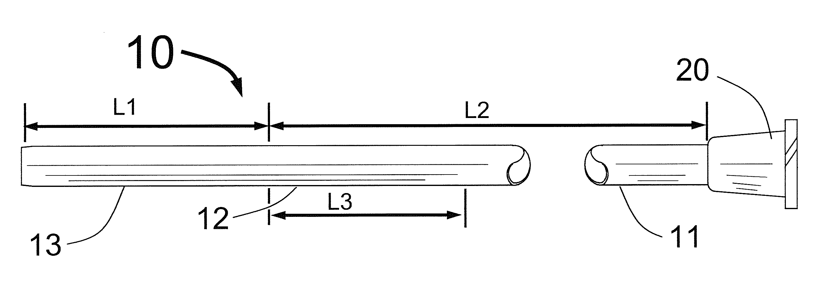
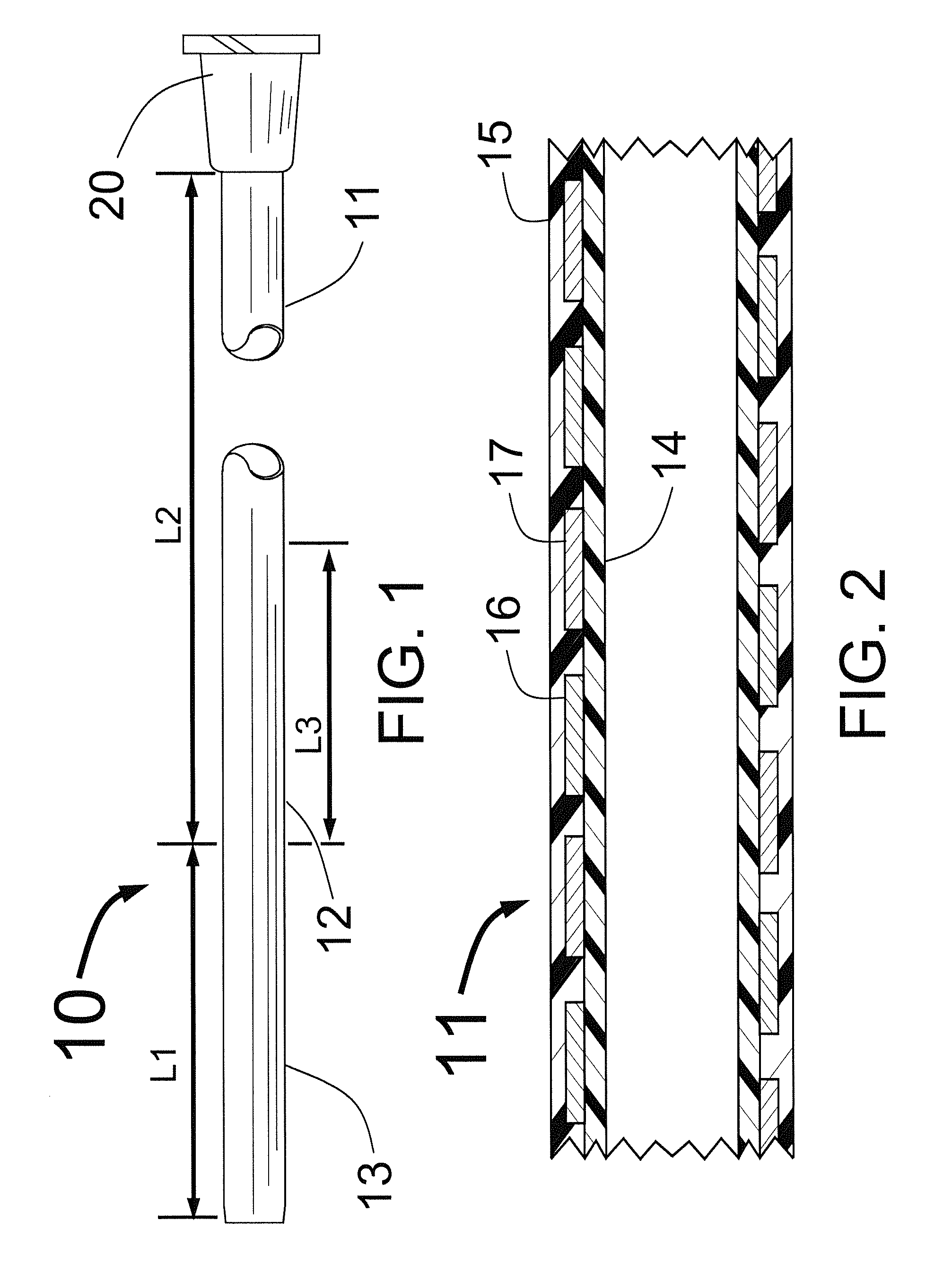
[0015]FIG. 1 shows a sheath 10 having a comparatively flexible distal portion 13 having a length L1, a comparatively long and stiff proximal portion having a length L2 and a comparatively short transitional section 12 with length L3. Typical lengths L1, L2 and L3 would be L1=10±5 cm, L2=75±10 cm and L3=3±3 cm. FIG. 1 also shows a Luer fitting at the proximal end of the sheath 10 which is typically used for injecting liquids through the sheath 10 or for connecting a Touhy-Borst fitting for performing carotid stenting. The Luer fitting with the Touhy-Borst fitting also allows for the passage of a dilator. Though it is not shown in FIG. 1, the present invention also envisions having a Touhy-Borst fitting fixedly attached at the sheath's proximal end instead of the Luer fitting.

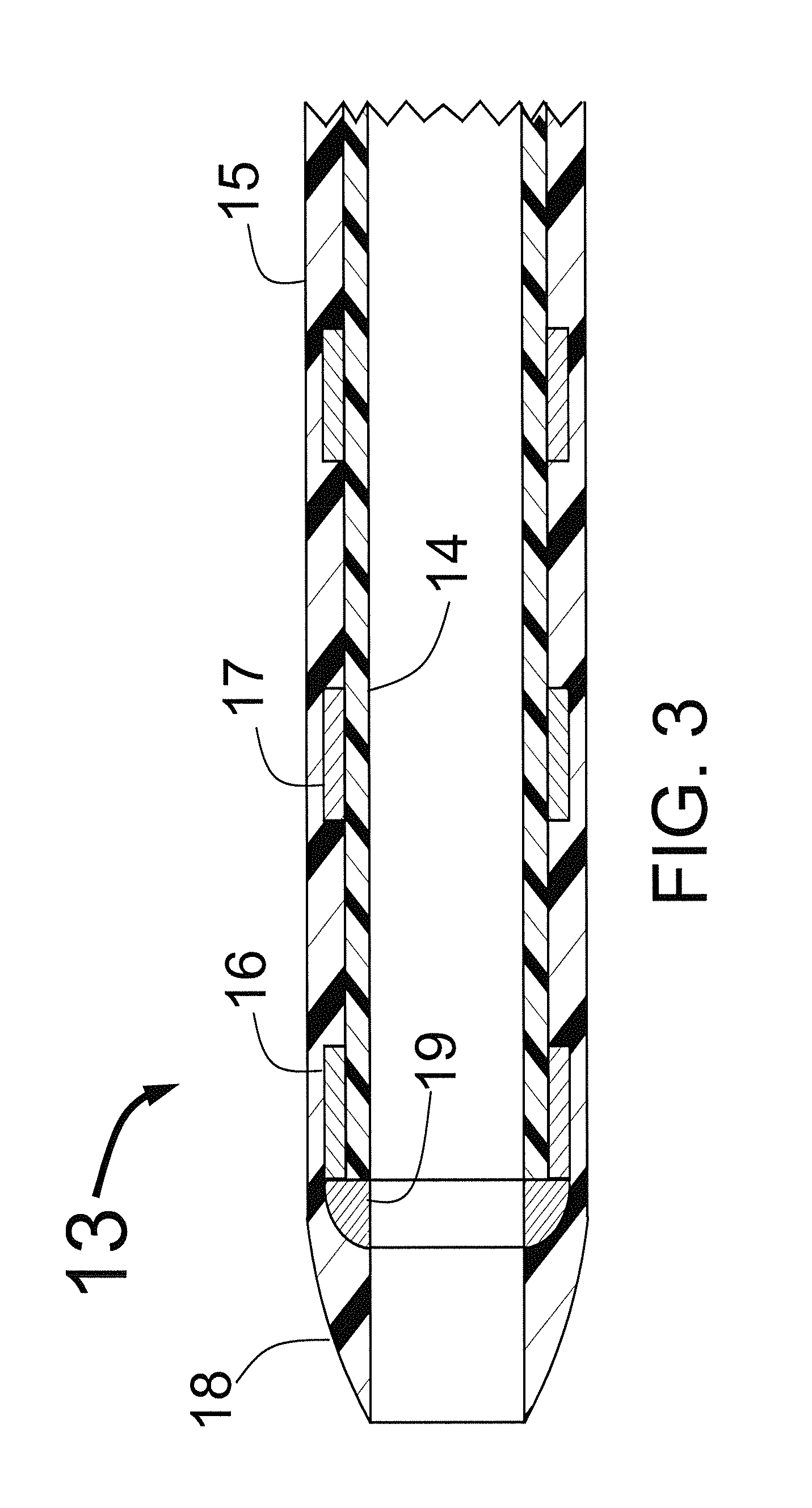
[0016]FIG. 2 shows a typical construction for the proximal portion 11 of the sheath 10. This portion of the sheath tubing would have an interior plastic coating 14 that would typically be formed from a lubricious...


PUM

PropertyMeasurementUnit
Lengthaaaaaaaaaa
Densityaaaaaaaaaa
Flexibilityaaaaaaaaaa

Abstract

A sheath to access a patient's vascular system where a portion of the length of the sheath is the proximal portion which has stiffer bending characteristics when taken with respect to a shorter distal section of the sheath which has increased flexibility with regard to bending characteristics.

Description

FIELD OF USE[0001]This invention is in the field of devices to assist in the placement of catheters through the skin to treat carotid artery obstructive disease.BACKGROUND OF THE INVENTION[0002]At the present time, physicians often treat carotid artery obstructive disease with the placement of a stent. This stent is typically placed in the internal carotid artery, in the common carotid artery, or spanning both arteries with the distal portion of the stent in the internal carotid artery and the proximal portion of the stent in the distal common carotid artery. The start of this procedure necessitates the placement of either a long sheath or a guiding catheter into the common carotid artery proximal to the carotid stenosis to be treated. The placement of such a sheath or guiding catheter can often be extremely challenging due to the tortuous course for access from the aortic arch into the common carotid artery. This is particularly an issue when accessing the right common carotid arte...

Claims


Application Information

Patent Timeline
IPC IPC(8): A61F2/84
CPCA61M25/0045A61M2025/0681A61M25/0662A61M25/0053
Inventor FISCHELL, ROBERT E.FISCHELL, TIM A.
Owner FISCHELL INNOVATIONS
Why Eureka
Try Eureka