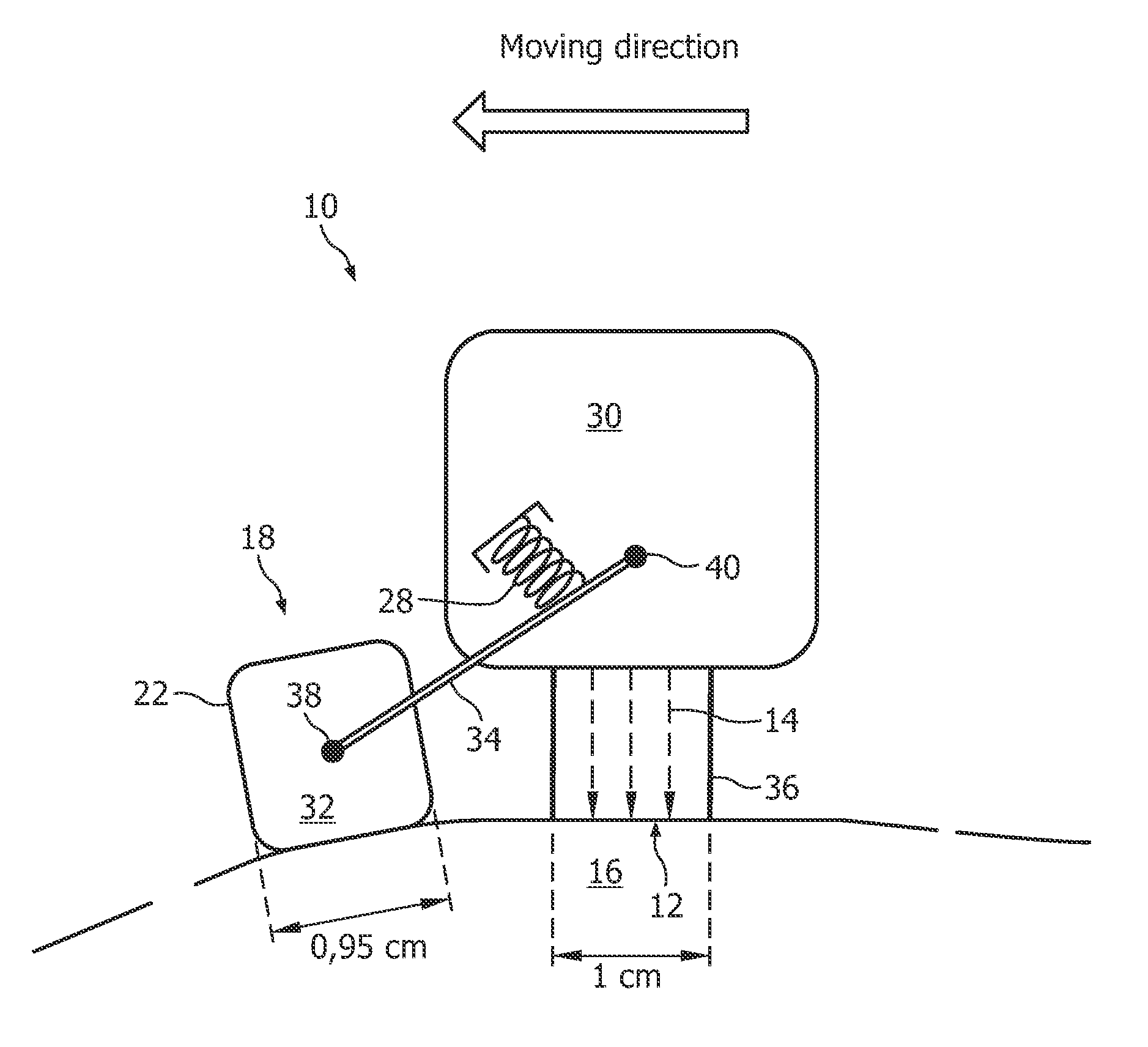
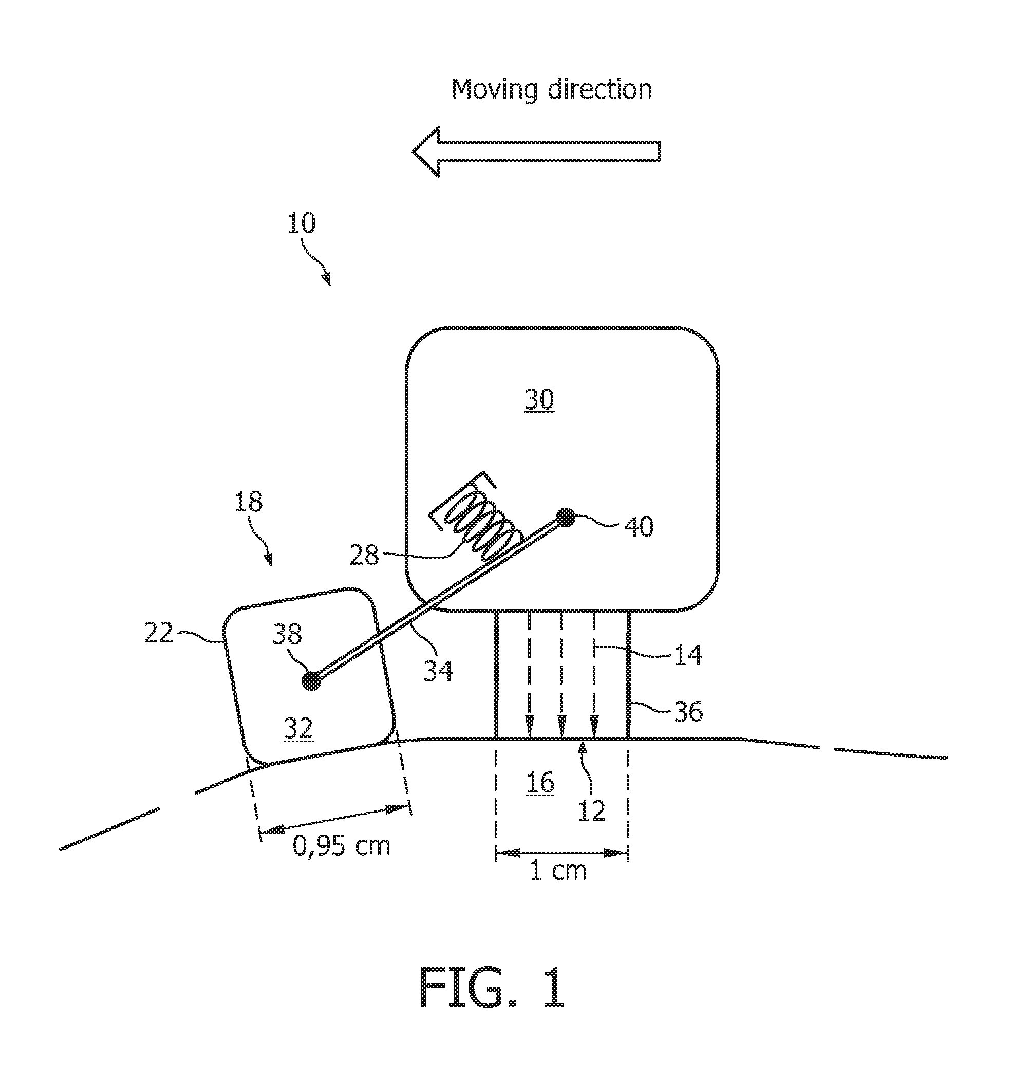
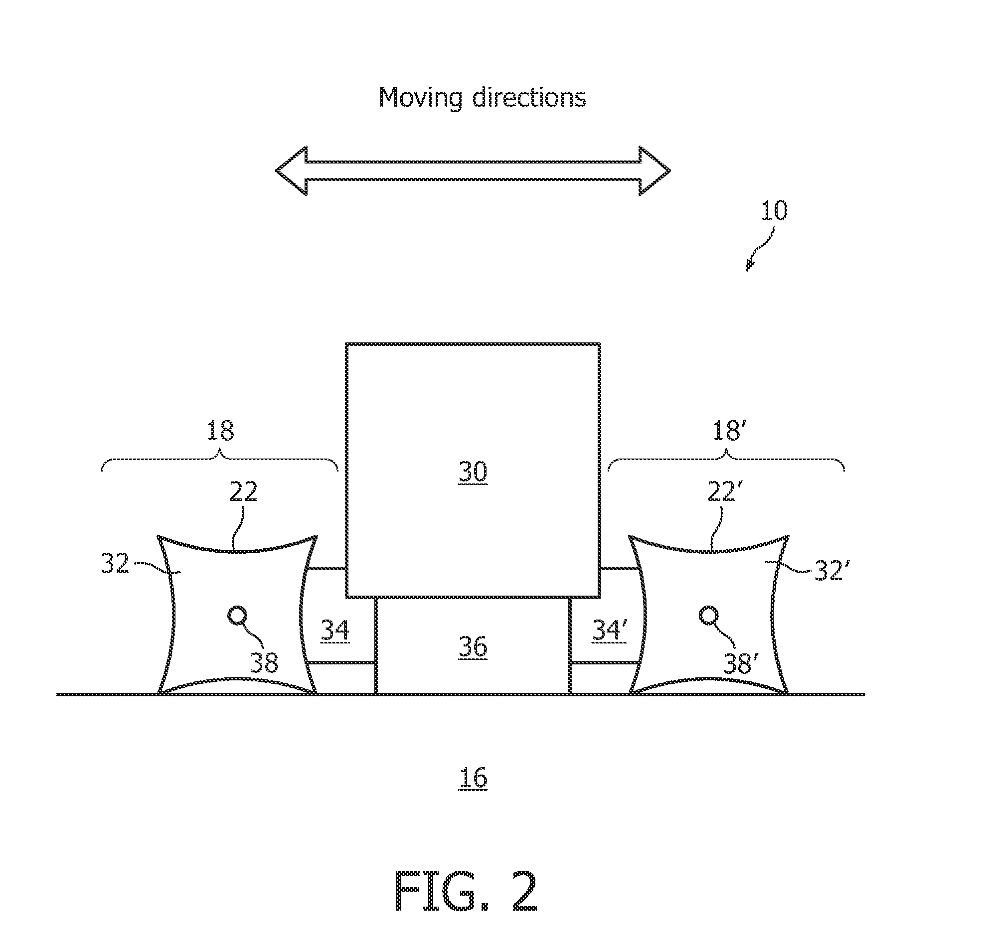
[0010]The invention provides a skin treatment device having a treatment window for treating skin through the treatment window and user guidance means for aiding a user of the skin treatment device in moving the treatment window along the skin in a stepwise manner, each moving step having a finite step width by which the treatment window is displaced, characterized in that the user guidance means are arranged separate from the treatment window and in that they deliver a tactile feedback
signal to the user at each moving step. The user may be either the patient himself, i.e. the person whose skin is treated, or a different person. Accordingly, the feedback signal may be delivered either to the skin of the patient or to the hand of the user who operates the skin treatment device, or to both. The tactile feedback signal enables the user to feel the transition between two consecutive moving steps and / or enables informing him when the treatment window has reached a new correct position for treatment. The tactile feedback signal may be generated in different ways, as will become clear from the discussion of various embodiments. Arranging the user guidance means separate from the treatment window allows for more flexibility in designing specific embodiments of the user guidance means, for example, when the step width of the skin treatment device is to be dimensioned so as to differ from the dimension of the treatment window. User guidance means that are situated separate from the treatment window can be easier to access mechanically, which may be desirable, for instance, when a specific version of user guidance means is to be replaced by an alternative version. Furthermore, the user guidance means can be arranged such that they come into contact chiefly with those parts of the skin that have not yet been treated, which will be advantageous if the skin is irritated by the treatment. Providing a tactile feedback signal about the stepwise motion of the treatment window has the
advantage that it can be delivered directly to those body parts implicated in the treatment, that is, either the skin of the patient or the hand of the user. Since a large part of the user's attention will be focused on his hand and / or on the skin that is treated (if the user is also the patient), the user is likely to be more attentive to a tactile signal as compared to an optical or acoustic signal, and will thus find the skin treatment device easier to use.
[0011]In a preferred embodiment of the invention, the step width measures between 90% and 100%, preferably about 95%, of the projection of the treatment window onto the moving direction. By choosing the step width to be somewhat smaller than the projection of the treatment window, a small overlap between consecutively exposed skin portions is achieved, which may ensure a more uniform
exposure of the total area of the skin that is treated in the case where the intensity of the light is substantially lower near the edge of the treatment window. In this context, it is preferable that the treatment window be essentially rectangular and aligned parallel to the moving direction. However, the treatment window may have any other shape. In particular, it could be oval, circular, or triangular. In the case of a treatment window having the shape of a regular triangle, the skin treatment device could be moved in a stepwise manner by rotating it in each moving step by 60° about one of the three axes extending from the three corners of the triangle perpendicularly to the treatment window.
[0012]According to a preferred embodiment of the invention, the user guidance means include at least one step roller. The step roller is understood to include a rotative element that can be rolled on the patient's skin in a stepwise manner, such that each rotative step of the step roller translates into a displacement of the treatment window along the skin, thereby defining the step width. A step roller can be realized, for example, by a wheel having a polygonal contour, wherein each side of the polygon has a length equal to the step width. Advantageously, the rotative element is rotatable about a
rotational axis parallel to the skin and perpendicular to the moving direction. The contour of the rotative member which comes into contact with the skin during the stepwise motion of the treatment window does not need to be cornered; it may in particular be circular, with a tactile signal being generated at particular rotational angles, for example, by providing a number of energetically preferred angles at which the rotational element assumes a minimum in internal
potential energy. Such
potential energy minima can be realized, for example, by providing an axle of the rotative element with notches, each notch corresponding to a specific rotational angle, together with a spring leaf that engages one of the notches when the rotational angle comes to coincide with one of the preferred angles and which disengages when the rotative element is rotated out of the preferred angle. A polygonal contour is likely to provide a firmer position of the rotative element on the skin between two consecutive moving steps, while a rotative element having a circular contour may be more comfortable to roll.
[0014]According to another aspect of the invention, the user guidance means are elastically biased toward the skin, preferably by means of a spring. Thereby it is ensured that the user guidance means stay in firm mechanical contact with the skin, provided the user holds the skin treatment device sufficiently close to the skin. This then ensures that the tactile signal is correctly transmitted to the user. In embodiments where only the user guidance means are to contact the patient's skin while the rest of the skin treatment device does not contact the skin, the elastic force felt by the user (either via his or her hand, and, if the user is also the patient, via his or her skin) helps the user to easily assess or “feel” the distance between the treatment window and the skin.
[0015]It may further be advantageous that the user guidance means are at least partly detachable from the skin treatment device. For example, the user guidance means may be fixed to the skin treatment device by means of a movable bar to ensure that the user guidance means follow the patient's body curvatures. The movable bar could also allow to put the user guidance means into a stow-away position, for situations in which the user guidance means are not needed or found inconvenient (for example, when applying the skin treatment device to confined areas of the body such as armpits). The user guidance means might also be designed to be completely detachable in the sense that they can be completely taken off the skin treatment device and put aside, for example, for cleaning.
[0016]According to a preferred embodiment of the invention, the user guidance means are arranged to trigger an emission of light via the treatment window after each moving step. Such a mechanism allows for a very convenient way of treating large areas of the patient's skin by displacing the skin treatment device in the described stepwise manner along the skin. After each displacement, felt by the user through the tactile feedback signal, the skin treatment device automatically emits the necessary quantity of light via the treatment window, preferably in the form of a short flash. Thus, the user will not have to actuate any other means for triggering the emission. Repositioning the device, preferably felt by overcoming some kind of
mechanical resistance generated by the user guidance means in cooperation with the skin, suffices to perform the next treatment step.


