Circuit interrupter including manual selector selecting different point-on-wave switching characteristics

a point-on-wave switching and interrupter technology, applied in the field of circuit interrupters, can solve the problems of large potential transformers, large size and weight, and large size of transformers

Inactive Publication Date: 2007-11-01
EATON CORP
View PDF6 Cites 27 Cited by
  • Summary
  • Abstract
  • Description
  • Claims
  • Application Information

AI Technical Summary

Problems solved by technology

Known medium voltage vacuum circuit interrupters employ potential transformers, which have a relatively large size and weight.
Such potential transformers are so lar

Method used


Image

  • Circuit interrupter including manual selector selecting different point-on-wave switching characteristics
  • Circuit interrupter including manual selector selecting different point-on-wave switching characteristics
  • Circuit interrupter including manual selector selecting different point-on-wave switching characteristics

Examples


example 1

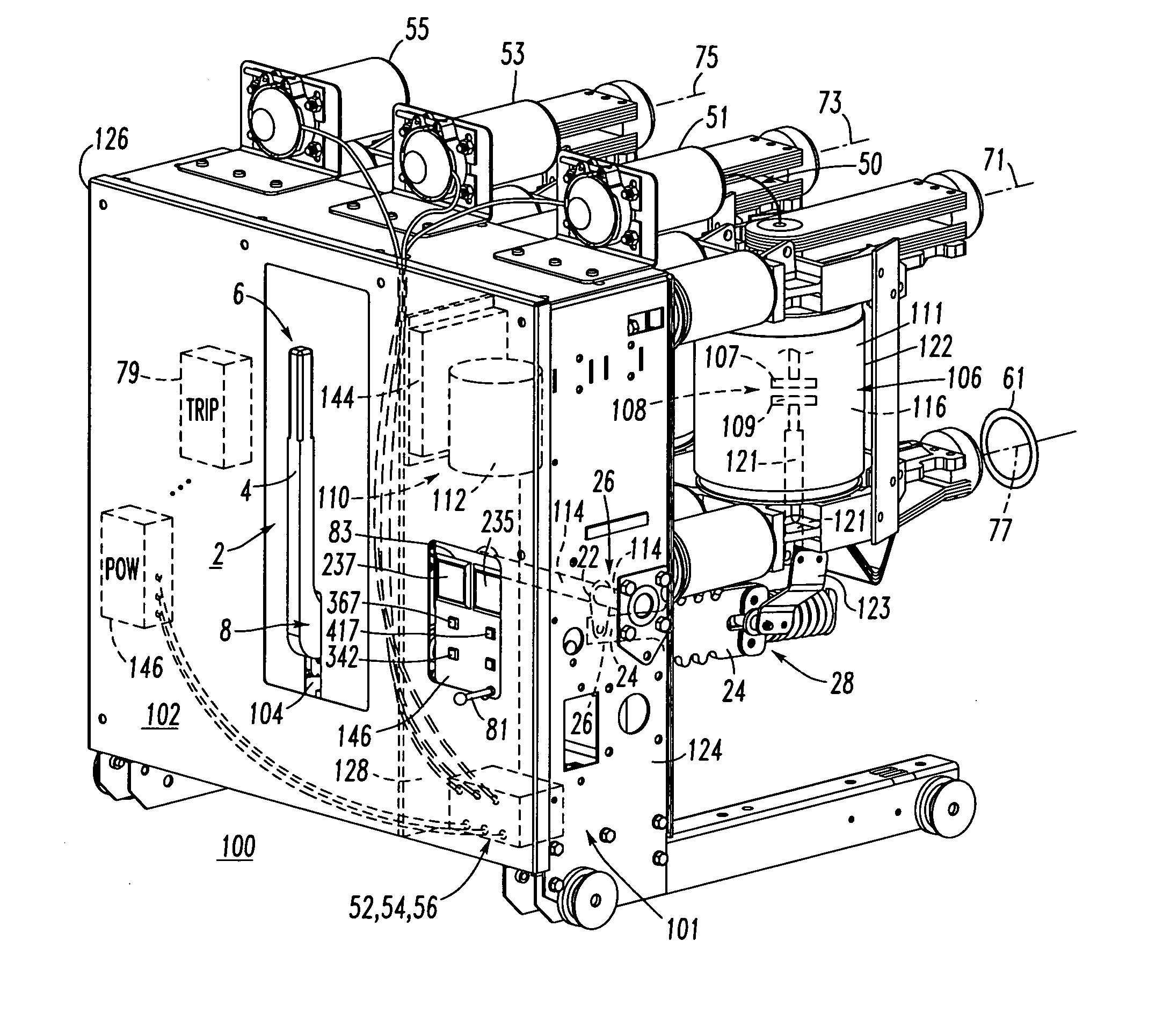
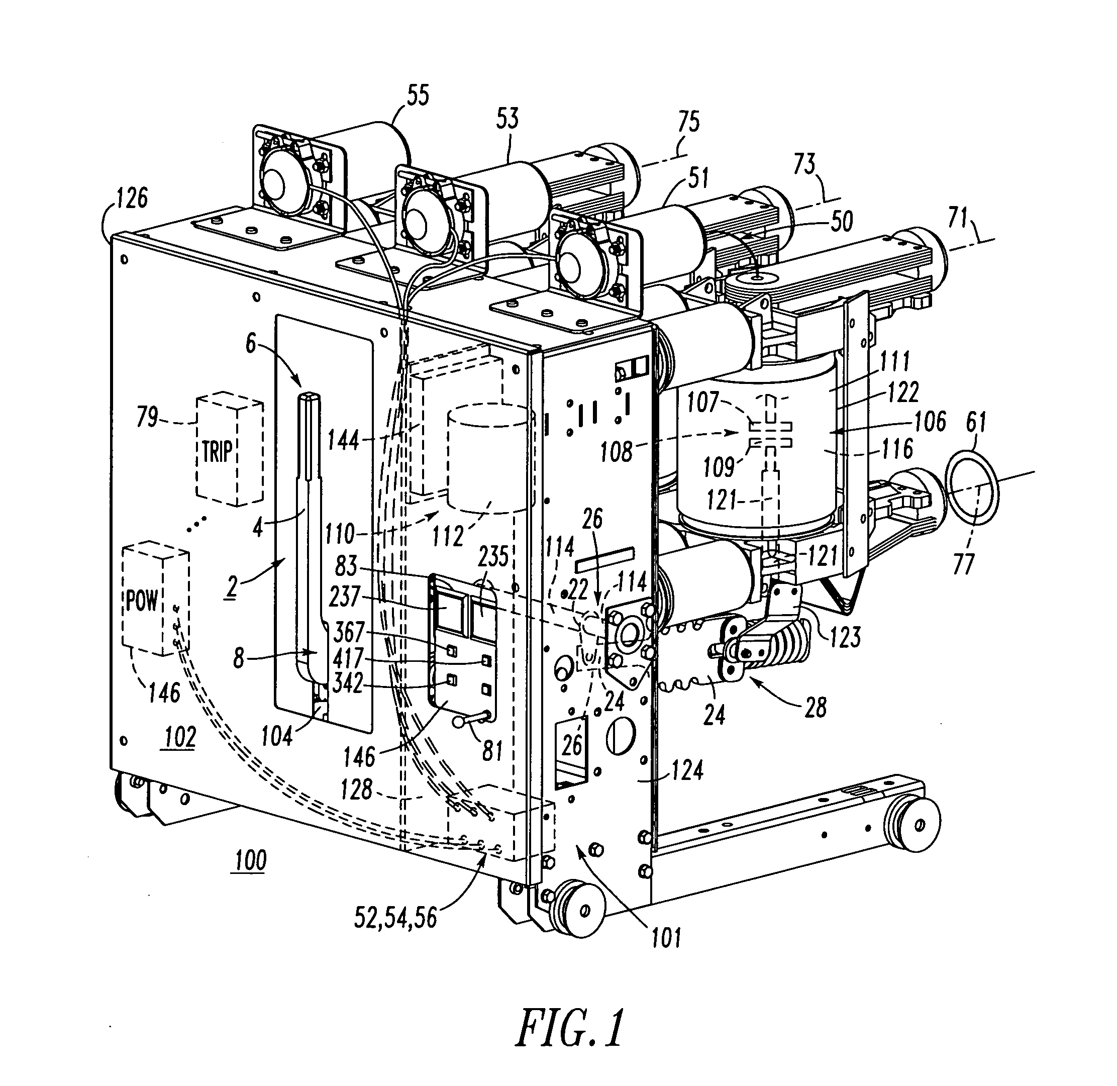
[0039] For example, the voltage sensors 51,53,55, as shown, are electro-optical sensors structured to sense a medium voltage from about 1 kV up to about 40 kV. These relatively small and light electro-optical voltage sensors, which are located on the top of the example circuit breaker housing 102, enable medium voltage measurement in a relatively compact package. These electro-optical voltage sensors galvanically isolate the signal to the POW controller 146 from the corresponding medium voltage being measured. An example of the electro-optical medium voltage sensors is an OptiSense 15 kV Class Voltage Sensor for Embedded Applications marketed by OptiSense Network, Inc. of Bridgeport, Tex.

example 2

[0040] For the example circuit breaker 100, the phase current signals are provided by external (e.g., located at the corresponding load power busses (as shown at bus 77) or within the switchgear enclosure (not shown)) current sensors 61,63,65, although the invention is applicable to current sensors located within the circuit breaker housing 102. For example, the current sensors 61,63,65 are current transformers structured to sense load current flowing through the separable contacts 108 of a corresponding one of the independent poles 101,103,105.

example 3

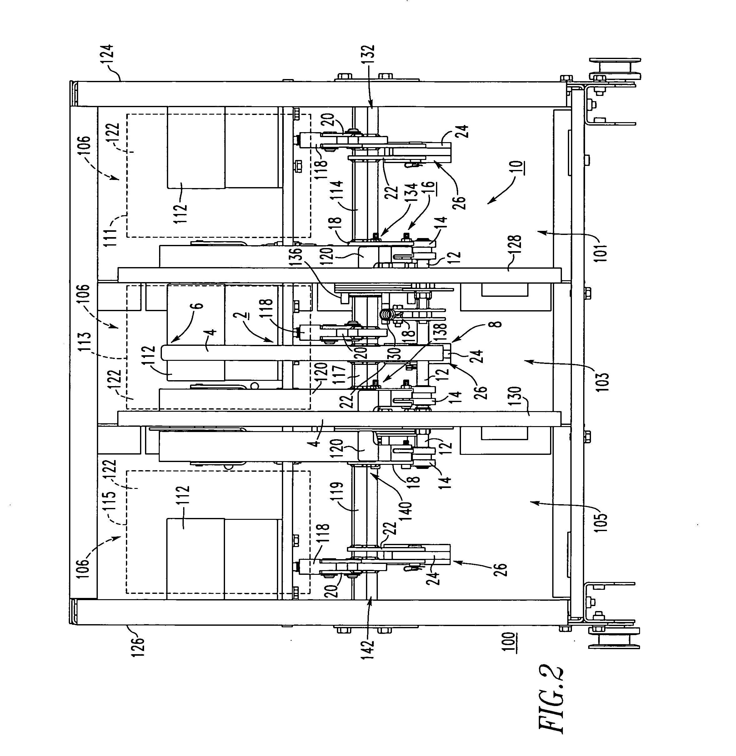
[0041] The three actuators112 are magnetically actuated actuators (e.g., linear actuators) structured to open and close the corresponding separable contacts 108. Alternatively, any suitable actuator may be employed. Non-limiting examples include Piezo actuators, electro-mechanical actuators and electro-pneumatic actuators.

[0042] The three example independent poles 101,103,105 are operated independently by three independently controlled operating mechanisms in order to achieve synchronous switching, also called point-on-wave (POW) switching. The circuit breaker 100 provides an integral three-phase voltage monitoring system and the POW controller 146 capable of performing the synchronous switching. The POW controller 146 (shown in hidden line drawing in FIG. 1) is housed by the circuit interrupter housing 102 (e.g., the POW controller 146 is integral with the housing 102) and cooperates with a number of the sensors 51,53,55,61,63,65 and the three actuators 112 of the independent pole...


PUM


Abstract

A circuit breaker includes a plurality of independent poles. Each of the independent poles includes separable contacts, sensors structured to sense a current and a voltage operatively associated with the separable contacts, and a magnetically actuated actuator structured to open and close the separable contacts. A manual selector, such as a rotary switch, is structured to select a point-on-wave switching characteristic from a plurality of different switching characteristics. A point-on-wave controller cooperates with the manual selector and with the sensors and the actuators of the independent poles to independently and synchronously open and close the separable contacts of the independent poles as a function of the point-on-wave switching characteristic selected by the manual selector.

Description

CROSS-REFERENCE TO RELATED APPLICATIONS [0001] This application is related to commonly assigned, concurrently filed: [0002] U.S. patent application Ser. No. ______ , filed ______, 2006, entitled “Manual Opening Device And Electrical Switching Apparatus Employing The Same” (Attorney Docket No. 05-EDP-484); and [0003] U.S. patent application Ser. No. ______ , filed______, 2006, entitled “Circuit Interrupter Including Point-On-Wave Controller And Voltage Sensors” (Attorney Docket No. 06-EDP-017).BACKGROUND OF THE INVENTION [0004] 1. Field of the Invention [0005] This invention pertains generally to circuit interrupters and, more particularly, to a circuit breaker including a plurality of independent poles which are controlled by a point-on-wave controller. [0006] 2. Background Information [0007] Circuit interrupters provide protection for electrical systems from electrical fault conditions such as, for example, current overloads and short circuits. Various circuit interrupters include ...

Claims


Application Information

Patent Timeline
IPC IPC(8): G01R31/327
CPCH01H33/666H01H9/563
Inventor ZHOU, XINLECCIA, BRAD R.ZOU, LIAN Q.
Owner EATON CORP
Why Eureka
Try Eureka