
Character highlighting control apparatus, display apparatus, highlighting display control method, and computer program

Inactive Publication Date: 2007-11-01
SONY CORP
View PDF4 Cites 6 Cited by
  • Summary
  • Abstract
  • Description
  • Claims
  • Application Information

AI Technical Summary

Benefits of technology

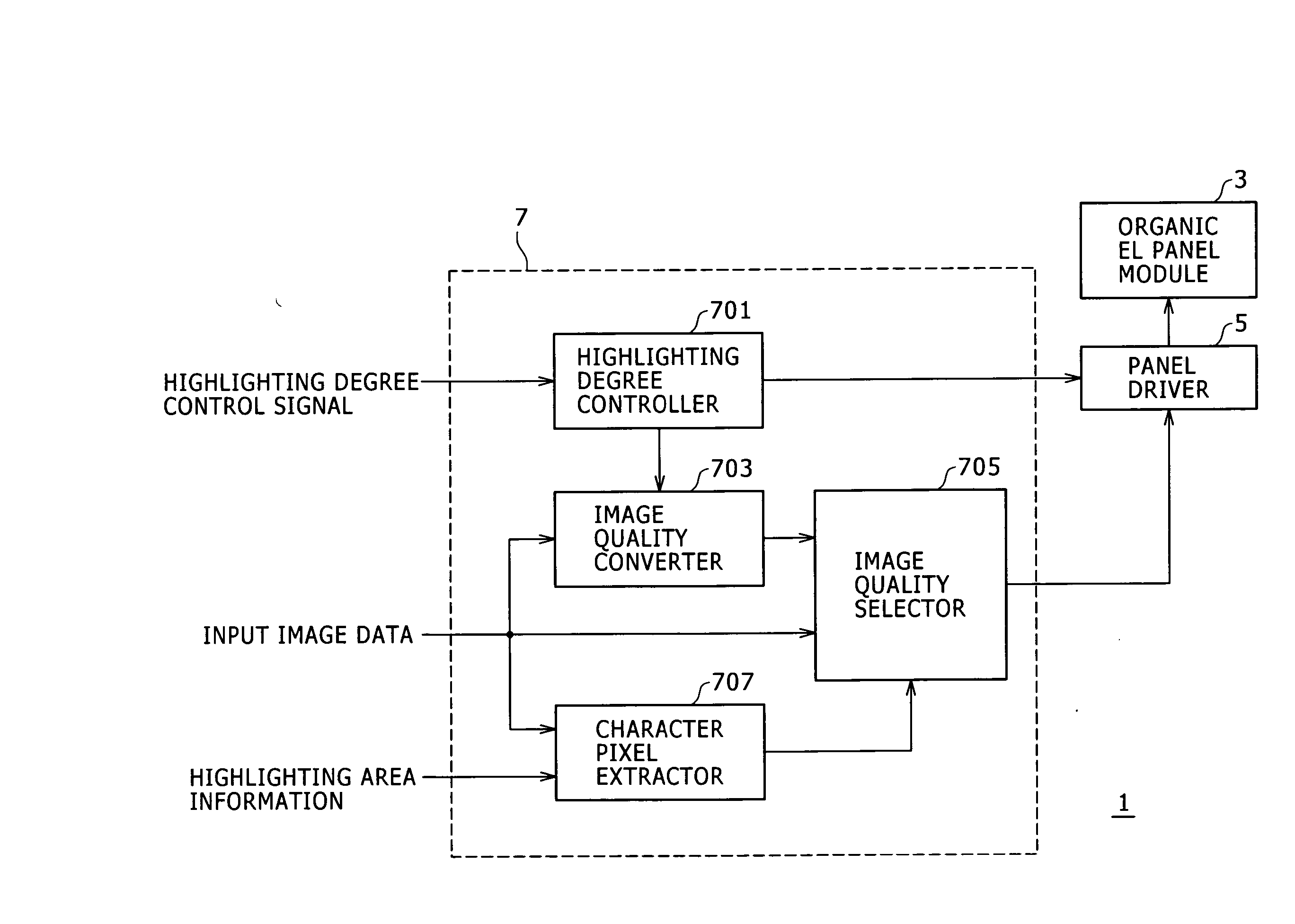
[0010] According to an embodiment of the present invention, a character highlighting control apparatus includes a character pixel extractor configured to extract a pixel corresponding to a character part from input image data, and a highlighting degree controller configured to carry out control in such a way that the maximum emission luminance of a display device is linked with input image data, to thereby selectively increase the emission luminance of an extracted pixel on a display screen and avoid increase of the emission luminance of a background part on the display screen.

Problems solved by technology

In the technique of the latter patent document, a highlighting area is decided at the time of image capturing, and hence optional specification of any highlighting area is difficult.

Method used


Image

  • Character highlighting control apparatus, display apparatus, highlighting display control method, and computer program
  • Character highlighting control apparatus, display apparatus, highlighting display control method, and computer program
  • Character highlighting control apparatus, display apparatus, highlighting display control method, and computer program

Examples


first embodiment

(A) First Embodiment

[0039] In a first embodiment of the invention, an organic EL panel as one example of a self-luminous display is employed as a display device.

(A-1) System Configuration

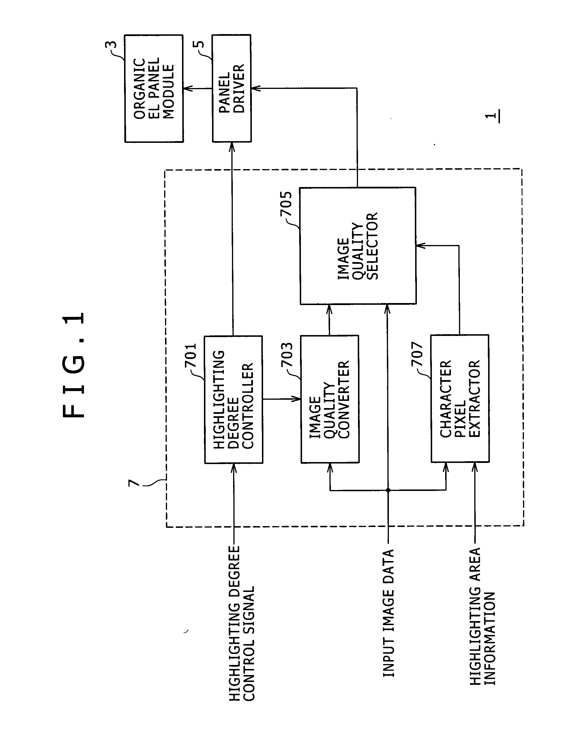
[0040]FIG. 1 shows a functional configuration example of an organic EL display that has a function to highlight a character part. An organic EL display 1 shown in FIG. 1 includes an organic EL panel module 3, a panel driver 5, and a character highlighting controller 7.

(a) Organic EL Panel Module

[0041] The organic EL panel module 3 is a display device in which display pixels of the three basic primary colors (R, G, B) are arranged in a matrix. The respective basic primary colors are generated by organic EL light-emitting elements.

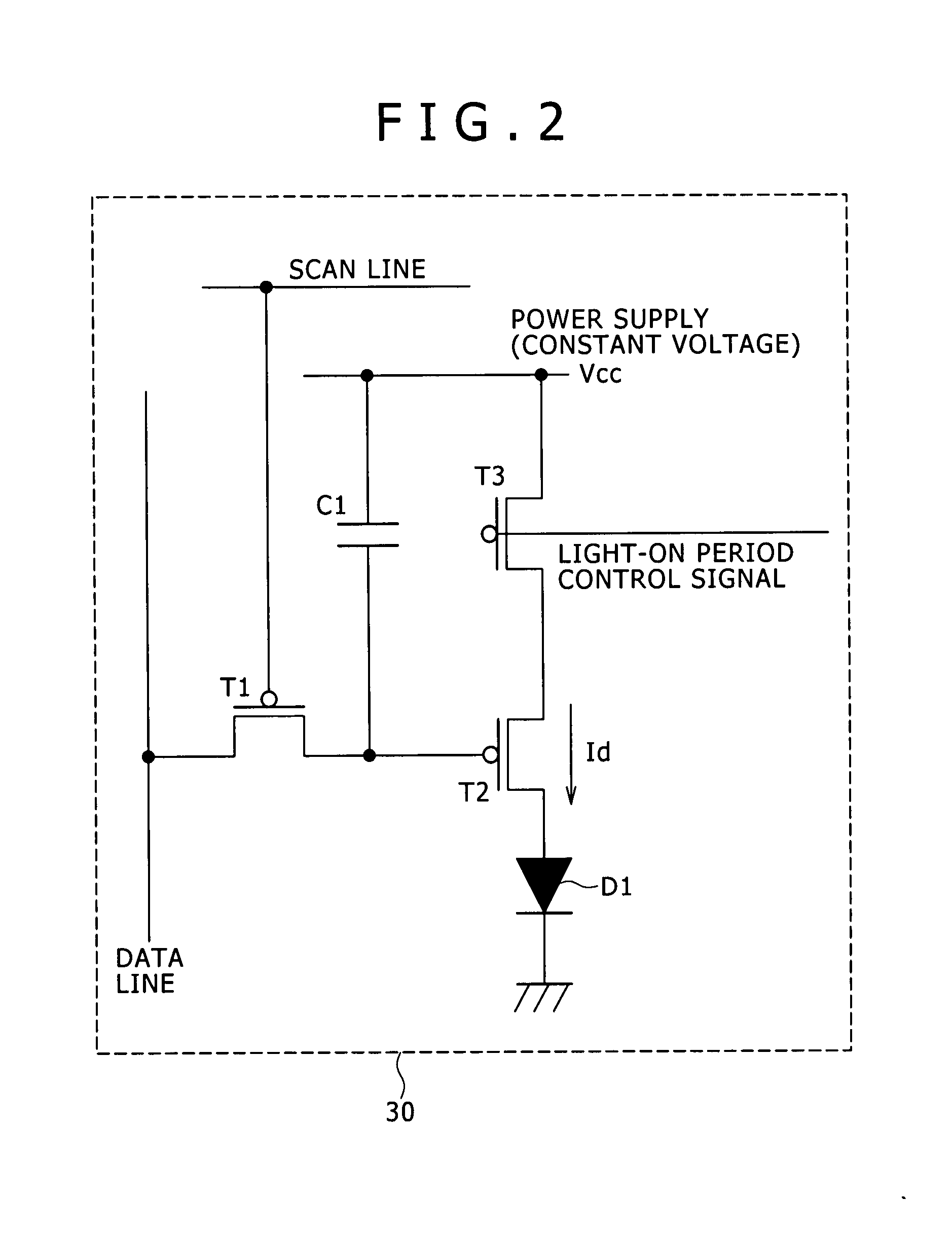
[0042]FIG. 2 shows an example of a drive circuit for controlling the emission operation of the organic EL element.

[0043] A drive circuit 30 is disposed at the intersection between a data line and a scan line. The drive circuit 30 includes a data switch element T1, a ...

second embodiment

(B) Second Embodiment

[0123] A description will be made below about an improved configuration that allows further enhancement of the visibility of a character part and reduction in power consumption.

[0124] The visibility of a character part is basically in proportion to the contrast between the character part and a surrounding background part. Furthermore, in the case of a display device in which self-luminous display elements are arranged, the power consumption is in proportion to the brightness of the screen.

[0125] Therefore, in a second embodiment of the present invention, the after-highlighting screen luminance of a background part is aggressively decreased so as to be lower than the before-highlighting screen luminance of the background part, to thereby simultaneously realize contrast enhancement and power consumption decrease.

(B-1) System Configuration

[0126]FIG. 15 shows a functional configuration example of an organic EL display to which this kind of function is added. Th...


PUM


Abstract

The present invention provides a character highlighting control apparatus including a character pixel extractor and a highlighting degree controller. The character pixel extractor is configured to extract a pixel corresponding to a character part from input image data. The highlighting degree controller is configured to carry out control in such a way that a maximum emission luminance of a display device is linked with input image data, to thereby selectively increase an emission luminance of an extracted pixel on a display screen and avoid increase of an emission luminance of a background part on the display screen.

Description

CROSS REFERENCES TO RELATED APPLICATIONS [0001] The present invention contains subject matter related to Japanese Patent Application JP 2006-127090 filed in the Japanese Patent Office on Apr. 28, 2006, the entire contents of which being incorporated herein by reference. BACKGROUND OF THE INVENTION [0002] 1. Field of the Invention [0003] The present invention to be described in this specification relates to a technique for enhancing the visibility of a character part. [0004] The embodiments of the invention proposed by the present inventors encompass a character highlighting control apparatus, display apparatus, highlighting display control method, and computer program. [0005] 2. Description of the Related Art [0006] Japanese Patent Laid-open No. 8-320679 discloses a displaying technique for highlighting a specific display area independently of the other area. [0007] Furthermore, Japanese Patent Laid-open No. 2004-172879 discloses a technique for, in reproduction and displaying of a ...

Claims


Application Information

Patent Timeline
IPC IPC(8): G09G5/02
CPCG09G3/3208G09G5/024G09G5/24G09G5/02G09G2320/0276G09G5/10G09G2320/0238G09G2320/0686G09G3/30G09G3/32G09G5/28
Inventor OZAWA, ATSUSHITADA, MITSURU
Owner SONY CORP
Learn More